Basic Welding Symbols
To ensure effective communication between professionals (such as welder, inspector, & engineers), welding symbols are used to convey important information about welds.
For this, it is must to know what the basic welding symbols & how to read them? In this blog post, we will explore the basic welding symbols every beginner should know.
Introduction to Welding Symbols
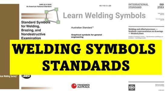
Welding symbols are a standardized system as per standards (e.g., AWS A2.4 (downloads for free) or ISO 2553) of visual representations used to communicate the desired weld type, size, and other details between designers, engineers, and welders.
These symbols are typically found on blueprints and technical drawings to quickly convey the necessary information without using lengthy descriptions but instead shown as geometrical representations, called welding symbols.
The American Welding Society (AWS) has established a set of standards for welding symbols, known as AWS A2.4, which is widely adopted in the United States and internationally.
Basic Components of Welding Symbols
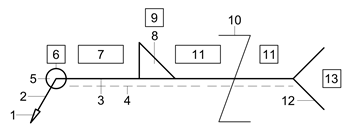
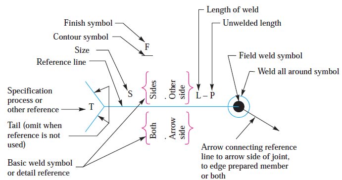
A welding symbol consists of several components:
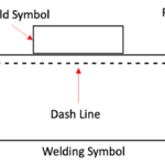
- Reference Line: A horizontal line that serves as the foundation for the welding symbol. All other elements are placed in relation to this line.
- Arrow Line: An arrow connecting the reference line to the joint location on the drawing. The arrow can be straight, curved, or jagged, depending on the specific weld type.
- Tail: An optional part of the welding symbol, located opposite the arrow. When included, the tail can contain additional information, such as welding process, specifications, or other notes.
- Weld Symbol (Most important): Weld symbol is placed on the horizontal line. It basically represent the physical shape of the weld. E.g., A fillet weld symbol resembles a triangular shape.
Basic Welding Symbols
Here are the essential welding symbols every beginner should be familiar with:
- Square Groove Welding Symbol
- V- Groove Welding Symbol
- Bevel Grove Welding Symbol
- U-Groove Welding Symbol
- J-Groove Welding Symbol
- Flare-V Groove Welding Symbol
- Flare Bevel Welding Symbol
- Scarf Joint Welding Symbol (Used for Brazing)
- Fillet Welding Symbol
- Plug Welding Symbol or Slot Welding Symbol
- Stud Welding Symbol
- Spot Welding Symbol
- Projection Welding Symbol
- Seam Welding Symbol
- Back or Backing Welding Symbol
- Surfacing Welding Symbol
- Edge Welding Symbol.
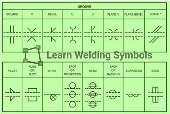
Some of these most commonly used basic Welding symbols are explained here:
1. Fillet Weld Symbol
A fillet weld is used to join two pieces of metal at a right angle. The symbol for a fillet weld is a right triangle that is placed either above or below the reference line, depending on the side of the joint where the weld is to be applied.
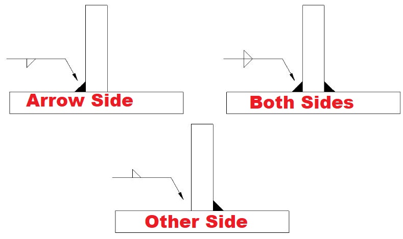
Further, Fillet Welds can be:
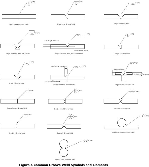
2. Groove Weld Symbol
A groove weld is a weld that fills the space between two workpieces to create a single, continuous piece of metal.
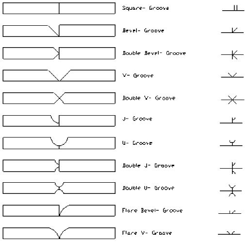
The symbol for a groove weld is a simple shape (such as a square, rectangle, or triangle) placed above or below the reference line. The specific type of groove weld is indicated by the shape used in the symbol.
3. Square Groove Weld Symbol
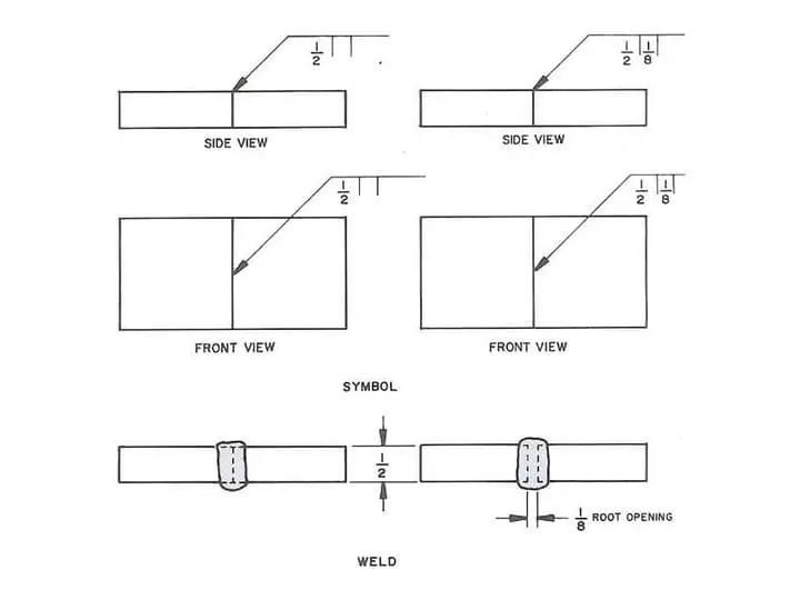
A square groove weld is a type of groove weld where the edges of the workpieces are parallel and square. The symbol for a square groove weld is a square placed above or below the reference line.
4. V-Groove Weld Symbol
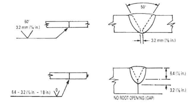
A V-groove weld is a type of groove weld where the edges of the workpieces are angled to create a V-shaped groove.
The symbol for a V-groove weld is an angled line or triangle, indicating the included angle of the groove, placed above or below the reference line.
5. Bevel Groove Weld Symbol
A bevel groove weld is a type of groove weld where one workpiece edge is beveled, and the other edge remains square.
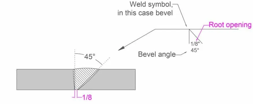
The symbol for a bevel groove weld is a triangle with a horizontal line through it, placed above or below the reference line.
6. U-Groove Weld Symbol
The U-groove weld is a type of joint design commonly used in welding applications. It involves creating a groove or channel in the shape of a “U” between the two metal components to be joined.
There are two primary types of U-Groove welding, based on the number of grooves involved in the process:

- Single U-Groove Welding: This type involves a single ‘U’ shaped groove on one side of the joint. A filler metal is then used to join the pieces together. This is generally used when one side of the weld is accessible.
- Double U-Groove Welding: This process involves a ‘U’ shaped groove on both sides of the joint. The double U-groove weld is used when both sides of the weld are accessible and offers a higher joint strength due to the greater weld area.
U-Groove Welding Symbols
Understanding welding symbols is critical for communicating design intentions. The American Welding Society (AWS) provides the standard symbols used in welding documentation.
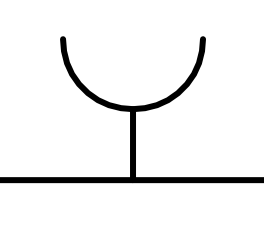
A U-groove weld symbol appears as a half-circle (U shape) placed at the reference line. Furthermore, the symbol’s placement – above or below the reference line – signifies if the weld is on the arrow side or the other side of the joint.
Single U-Groove Welding Symbol
The single U-groove welding symbol appears as a half-circle (U-Shape) on the reference line’s side where the weld will be made. The symbol’s orientation (opening upward or downward) doesn’t change the meaning.

Double U-Groove Welding Symbol
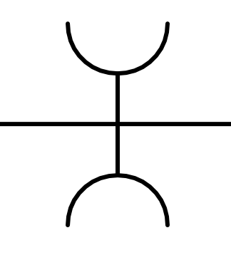
The double U-groove welding symbol consists of two half-circle (U-Shape) symbols, one above and one below the reference line, indicating U-grooves on both sides of the joint.
7. J-Groove Weld Symbol
J-groove welding, as the name suggests, involves creating a ‘J’ shaped groove in the joint between two pieces of material. J-Groove is a special type and usually created by machining to have precision dimeision.
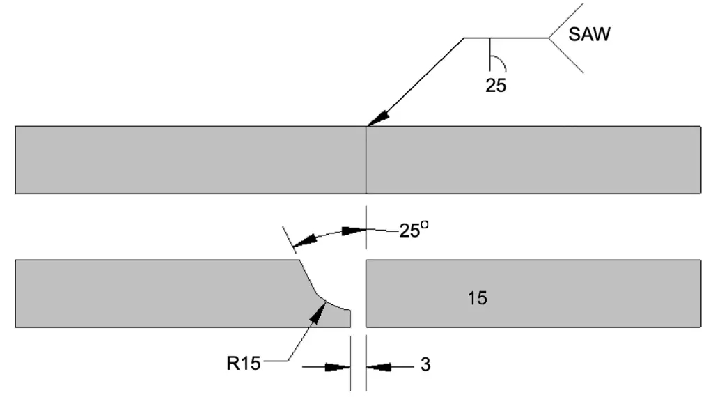
8. Flare Bevel Groove Weld Symbol
The flare bevel groove weld is a type of joint design commonly used in welding applications. It involves creating a groove or channel with a flared bevel shape between the two metal components to be joined.
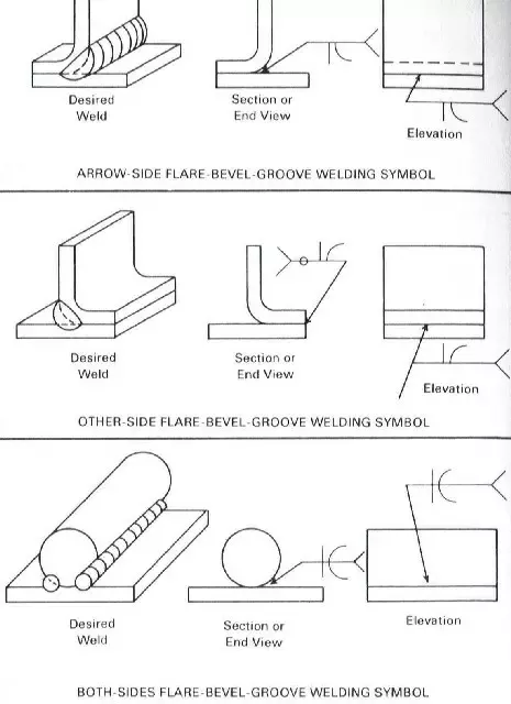
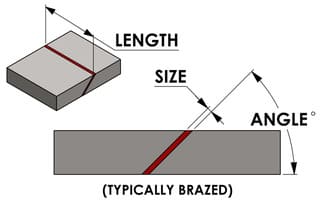
9. Scarf Joint Welding Symbol
The scarf joint welding symbol represents a specific type of joint design used in welding known as a scarf joint. The scarf joint is a type of butt joint where the ends of two metal components are beveled or tapered to form an angled surface.
10. Plug Weld Symbol
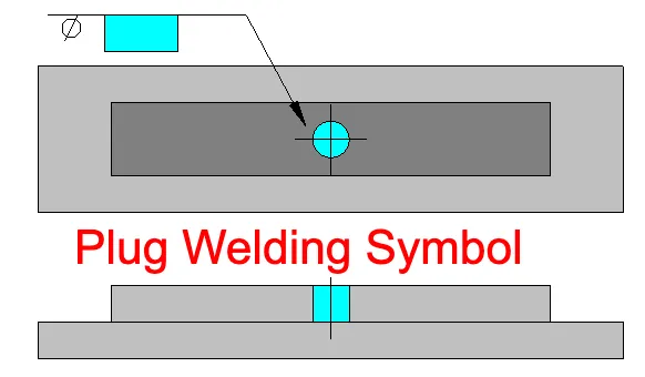
A plug weld is a type of weld used to join two overlapping metal pieces, typically by filling a predrilled hole. The symbol for a plug weld is a small circle placed above or below the reference line.
11. Slot Weld
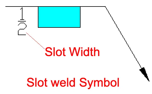
A slot weld is similar to a plug weld, but the hole is elongated instead of circular. The symbol for a slot weld is a small rectangle placed above or below the reference line.
12. Stud Weld Symbols
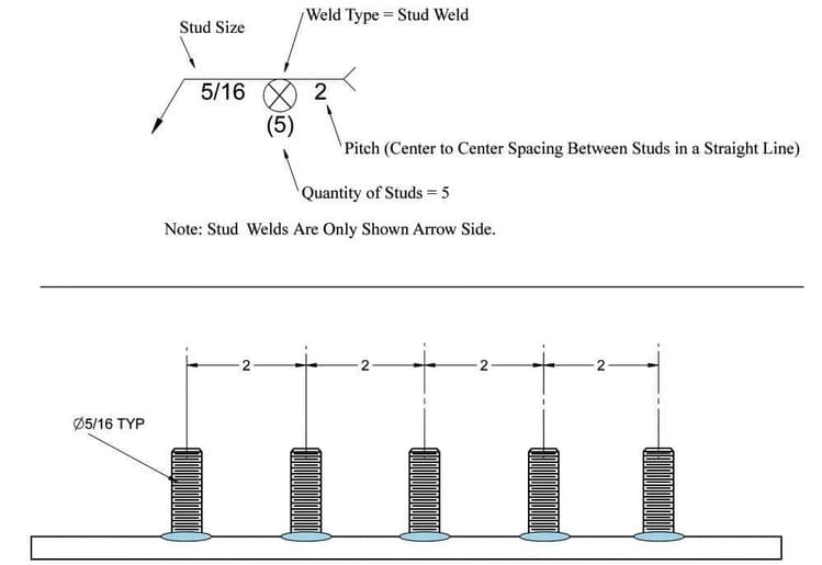
Stud weld symbols are graphical representations used in welding symbols to indicate the use of stud welding as a joining method. Stud welding involves the attachment of a metal stud or fastener to a base material through the application of heat and pressure.
In welding symbols, stud weld symbols typically consist of a circle placed on the reference line as shown in below example.
13. Spot Welding Symbol
The spot welding symbol is a graphical representation used in welding symbols to indicate the use of spot welding as a joining method.
Spot welding is a resistance welding process where two or more metal sheets are joined together by applying heat and pressure at specific points or “spots” on the surface.
In welding symbols, the spot welding symbol typically consists of a small circle. The symbol may also include additional elements such as dimensions, annotations, or tail to provide further details about the spot welding process.
14. Projection Welding Symbol
The projection welding symbol is a graphical representation used in welding symbols to indicate the use of projection welding as a joining method.
In welding symbols, the projection welding symbol typically resembles the spot welding symbol, which is a small circle or dot. However, the projection welding symbol includes additional indications to differentiate it.
For example, in the ISO system, the letter “P” is placed in front of the weld size to indicate a projection weld. In the AWS (American Welding Society) standard, the letters “PW” are placed in the tail of the reference line to represent a projection weld.
15. Seam Welding Symbol
Seam welding employs a process akin to spot welding, but it is carried out in an extended manner. Unlike plug or slot welding, it doesn’t necessitate any preliminary steps.
The weld penetrates the top surface and fuses with the other component via heat application. The emblem for seam welding resembles that of spot welding, though it includes two parallel lines.
16. Back weld and backing weld Symbol
Back weld and backing weld (backing run) Symbol are same and they are basic weld symbols.
In the AWS system, it’s possible to indicate whether a symbol represents a back weld, a backing weld, or a run by writing “BACK WELD” or “BACKING WELD” in the tail of the reference line, as illustrated in the figure below.

17. Weld Surfacing or Weld Overlay Welding Symbols
The height of surfacing weld/ weld overlay is always given on the left side of the weld symbol as shown in below example. The length of weld if required shall be mentioned on the right side of the weld symbol.

Conclusion
Understanding basic welding symbols is essential for anyone working in industries that involve welding or interpreting technical drawings.
By familiarizing yourself with these symbols, you can effectively communicate with other professionals and ensure that your welding projects are completed accurately and efficiently.
