Understanding Piping and Instrumentation Diagrams (P&IDs): A Comprehensive Guide
Piping and Instrumentation Diagrams (P&IDs) Piping and Instrumentation Diagrams (P&IDs) are essential documents in the design, construction, and operation of industrial plants. They provide an in-depth view of the process flow, equipment, and instrumentation used …
Written by: Kumar
Published on:
Piping and Instrumentation Diagrams (P&IDs)
Piping and Instrumentation Diagrams (P&IDs) are essential documents in the design, construction, and operation of industrial plants. They provide an in-depth view of the process flow, equipment, and instrumentation used in a facility. This guide will explore P&IDs and their role in the engineering world, helping you gain a better understanding of their components and how they are used in various industries.
Who use P&IDs?
P&IDs, which are essential for maintaining the safe and efficient operation of a process system, hold significance for individuals responsible for this task. Here are a few instances where an operator, mechanic, or technician may find it necessary to refer to a P&ID:
Planning and organizing activities related to the process system.
Creating a job safety analysis (JSA) for a specific task.
Implementing lockout procedures before repairing or replacing process equipment.
Troubleshooting issues that arise during operation.
Preparing for emergencies and effectively handling emergency situations.
Conducting process hazard reviews.
Providing training to new employees.
While P&IDs serve as a valuable source of information, they are not the sole resource required for completing a task. In some cases, additional sources may need consultation. For example, when replacing an instrument, referring to instrument specification sheets becomes necessary to gather details like the manufacturer’s name.
What is a Piping and Instrumentation Diagram (P&ID)?
A P&ID or also called Piping and Instrumentation Diagram or Drawing is a detailed graphical representation of the process flow, equipment, and instrumentation within a plant or facility. These diagrams depict the physical relationships between equipment, piping, and system components, as well as the instrumentation and control systems used to monitor and control processes.
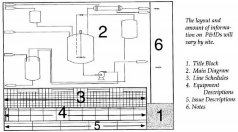
P&IDs Drawing Example
The primary component of the P&ID is referred to as the Main Drawing. This section contains information that is visually represented through symbols and lines. In the Main Drawing of an actual P&ID, you will come across the following symbols and lines:
Equipment: Representations of various process equipment such as pumps, tanks, vessels, compressors, and heat exchangers.
Piping connecting pieces of equipment: Depictions of pipes that connect different pieces of equipment, indicating the flow of fluids or materials between them.
Instruments: Symbols indicating the presence of instruments used for measurement, control, or monitoring purposes, such as pressure gauges, temperature sensors, level indicators, flow meters, and valves.
Lines connecting instruments: Lines that connect instruments to each other or to other components, signifying the flow of signals or data between them.
Instrument control loops: Illustrations of control loops that involve instruments, controllers, and final control elements (e.g., valves), showcasing the process control and regulation within the system.
P&IDs consist of various symbols and notations that represent different elements within a plant. Some of the primary components include:
Equipment: Tanks, pumps, compressors, heat exchangers, and other process equipment are represented using standard symbols. Equipment is typically labeled with a unique identifier for easy reference.
Piping: Piping is represented by lines connecting different equipment and process components. Line numbers and specifications, such as pipe size, material, and insulation, are included.
Valves: Valves control the flow of fluids through piping systems. Various symbols represent different types of valves, such as gate, globe, check, and relief valves.
Instrumentation: Instruments measure and control process variables such as pressure, temperature, flow, and level. Each instrument is typically assigned a unique tag number, which corresponds to its function and location within the system.
Control Systems: P&IDs show the relationships between control elements, such as sensors, transmitters, controllers, and final control elements like control valves. These relationships are represented by dashed lines connecting the various components.
Reading and Interpreting P&IDs
To effectively read and interpret P&IDs, it is essential to become familiar with the standard symbols and notations used in these diagrams. Once you have a solid understanding of the symbols, you can start analyzing the overall process flow, equipment arrangement, and control schemes within a facility.
Equipment Symbols
In some instances, a P&ID includes descriptions of the essential equipment depicted in the drawing. This information is typically found in block number 4, as mentioned earlier. The equipment descriptions on a P&ID may be presented as notes at the bottom of the main drawing or in other formats. Regardless of the location, the equipment descriptions may encompass the following information, depending on the type of equipment:
Unique equipment number: A distinct identifier that appears both on the equipment itself and on the corresponding equipment symbols on the P&ID.
Capacity: The maximum or intended capacity or volume that the equipment can handle or process.
Size: The physical dimensions or specifications of the equipment, such as length, width, height, or diameter.
Material of construction: The specific material used in the construction of the equipment, which can vary depending on factors like chemical compatibility, pressure requirements, or temperature conditions.
Vendor and model number: If relevant, the name of the manufacturer or vendor responsible for producing the equipment, along with the model number or designation.
Temperature and pressure information: Pertinent details about the operating temperature and pressure ranges for the equipment, which are crucial for ensuring safe and effective operation.
Horsepower of pumps: Specifically for pumps, the power rating indicated in terms of horsepower, which indicates the mechanical power output of the pump.
These equipment descriptions serve to provide important details about the equipment’s specifications, characteristics, and relevant parameters for proper understanding and operation within the process system.
The equipment number is typically displayed within or in close proximity to the equipment symbol on the P&ID. In cases where the symbol is relatively small, the equipment number may be placed nearby for visibility. It is important to note that the equipment number assigned to each piece of process equipment within the plant should be unique, meaning that no other equipment in the facility should bear the same number.
Additionally, specific information about a particular equipment item, such as a tank, may also be directly written on the equipment itself, on-site. This can provide additional details or specifications that are specific to that particular piece of equipment, complementing the information found on the P&ID. This on-site labeling helps ensure clarity and accuracy when referring to the equipment during maintenance, operation, or troubleshooting activities.
The main Equipment symbols used in P&IDs drawings are shown below:
Instrument Symbols in P&ID
Instrument symbols in P&ID represent various types of instruments used for measuring, monitoring, controlling, or indicating process parameters within a process system. These symbols provide a visual representation of the instruments and their functions. Here are some commonly used instrument symbols in P&ID:
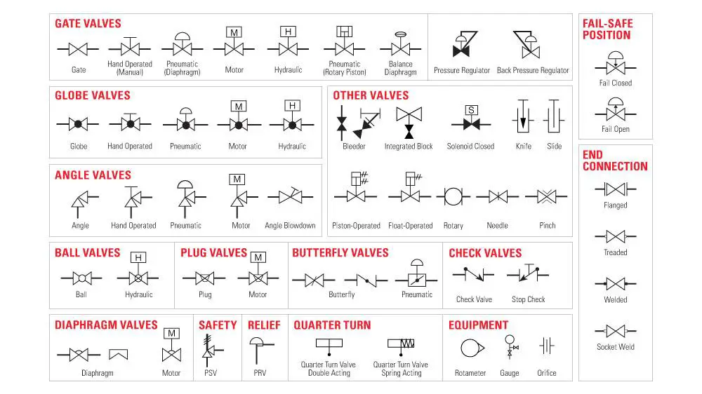
Valves Symbols in P&ID Drawing
Valve symbols in P&ID drawings represent different types of valves used to control the flow, pressure, or direction of fluids within a process system. These symbols provide a visual representation of the valves and their functions. Here are some commonly used valve symbols in P&ID:
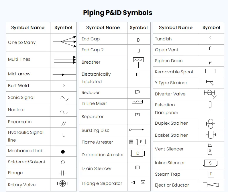
Piping Symbols in P&ID Drawing
Piping symbols in P&ID drawings represent different types of pipes, fittings, and components used to convey fluids within a process system. These symbols provide a visual representation of the piping layout and connections. Here are some commonly used piping symbols in P&ID:
P&ID Symbols for Pumps
P&ID symbols for pumps represent the different types of pumps used in process systems to move fluids from one location to another. These symbols provide a visual representation of the pump type and its basic function. Here are some commonly used P&ID symbols for pumps:
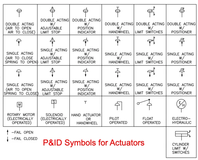
P&ID Symbols for Actuators
An actuator is the part that controls the valve. P&ID symbols for actuators represent the devices responsible for controlling the movement or positioning of valves, dampers, or other mechanical components within a process system. Here are some commonly used P&ID symbols for actuators:
Pneumatic Actuator.
Electric Actuator.
Hydraulic Actuator.
Motor-Operated Actuator.
When reviewing a P&ID, follow these steps:
Identify the primary equipment and process components.
Trace the flow of materials through the system, noting the direction of flow indicated by arrows on piping lines.
Examine the valves and other piping components to understand their role in controlling and directing flow.
Review the instrumentation and control systems, paying attention to the relationships between sensors, controllers, and final control elements.
Look for safety and relief devices, such as pressure relief valves and safety interlocks, to understand the safety measures in place.
P&IDs provide numerous benefits to engineers, operators, and maintenance personnel, including:
Streamlined Design: P&IDs enable engineers to visualize the entire process flow, making it easier to identify potential design improvements and optimize system efficiency.
Simplified Construction and Commissioning: P&IDs serve as a reference for construction crews and help ensure that equipment is installed according to design specifications.
Enhanced Operation and Maintenance: P&IDs allow operators and maintenance staff to quickly locate and troubleshoot issues within the plant, reducing downtime and increasing overall productivity.
Improved Safety: P&IDs provide a comprehensive view of safety devices and interlocks, helping to ensure that all safety measures are in place and functioning correctly.
Conclusion
Piping and Instrumentation Diagrams (P&IDs) are indispensable tools in the design, construction, and operation of industrial plants. By understanding their components and learning how to read and interpret them, you can enhance your ability to work effectively with these critical engineering documents in various industries.
Kumar is a highly experienced welding professional and author known for his expertise in welding symbols. With certifications including IWE, AWS-CWI, and ASNT NDT Level III.