Demystifying Weld Symbols in the UK: A Comprehensive Guide
Weld symbols play a crucial role in sheet metal fabrication, enabling effective communication between designers and welders. In the UK, weld symbols adhere to specific standards and conventions to ensure accurate representation and understanding of …
Weld symbols play a crucial role in sheet metal fabrication, enabling effective communication between designers and welders. In the UK, weld symbols adhere to specific standards and conventions to ensure accurate representation and understanding of welded joints.
In this blog post, we will delve into the world of weld symbols in the UK, exploring their significance, standards, and commonly used symbols.
Understanding Welding Standards
In the UK, the weld symbols are governed by the EN ISO 2553:2013 standard, which provides rules for the symbolic representation of welded, brazed, and soldered joints on drawings.
This standard supersedes the previously used BS EN 22553:1995. It’s worth noting that the 2013 version of EN ISO 2553 has been replaced by BS EN ISO 22553:2019.
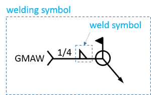
Weld Symbol vs Welding Symbol
In welding, there are two important parts called the “Welding Symbol” and the “weld symbol.” The Welding Symbol is the overall representation of the weld, while the weld symbol focuses on specific details.
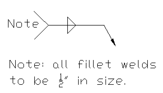
Sometimes, there is a part called the Tail in the weld symbol, but it’s not always used. The Tail provides extra information about the weld, such as the welding process, a detailed drawing, or the type of electrode used.
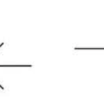
fillet-weld-tail-section
It’s like a space for additional helpful notes that don’t have their own place in the symbol. For example, in a Stitch Weld, if there are numbers on the Tail, they show the size of the weld and the gap between the welds.
Another important part is the Reference Line, which is always drawn horizontally. It tells us where all the other welding symbols are connected. From the Reference Line, there is a Leader Line that connects the head of the Arrow to the reference line.
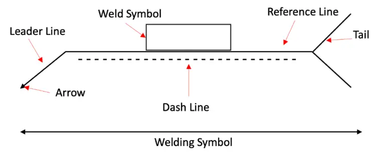
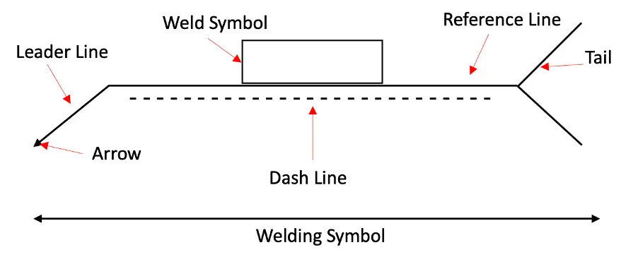
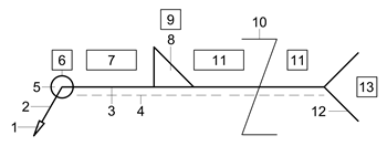
Components of a Weld Symbol
A basic weld symbol consists of several elements:
Tail: The tail is an optional component that provides additional information about the weld. It can include details about the welding process, electrode specifications, or any relevant notes that enhance the understanding of the weld.
Reference Line: The reference line serves as the base for all other welding symbols. It is always drawn horizontally and provides a point of connection for the rest of the symbols.
Arrow: The arrow indicates the location and direction of the weld. If the weld symbol is placed above the reference line, it applies to the arrow side of the joint. Conversely, if it is placed below the reference line, it applies to the opposite side of the joint.
Dash Line: In ISO systems, a dash line may be present above or below the reference line. Its placement does not affect the interpretation of the weld symbol. However, in symmetrical welds, the dash line is omitted, indicating that the weld should be performed on both sides of the joint.
In the UK, various elementary weld symbols are employed to represent specific joint configurations and welding processes. Some commonly used symbols include:
Square Groove Weld
Single Bevel Groove Weld with Broad Root Face
Single V Groove Weld
Single U Groove Weld
Backing Weld
Single J Groove Weld
Fillet Weld
Edge Weld
Spot Weld
Seam Weld
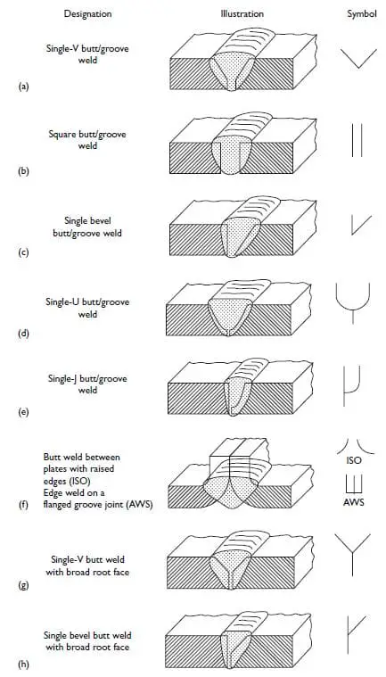
Basic or Elementary Welding Symbols
When it comes to elementary welding symbols according to BS 2553 (British Standard), they are used to represent specific joint configurations and welding processes. Here are some of the commonly used elementary welding symbols:
Square Groove Weld: Represented by a square-shaped symbol, it indicates a joint where the edges of the base metal are square and the weld is made in the groove between them.
Single Bevel Groove Weld with Broad Root Face: This symbol depicts a joint with one beveled edge and a wider root face. The beveled edge is where the weld will be applied.
Single V Groove Weld: Shown by a V-shaped symbol, it illustrates a joint with two pieces of metal meeting at a V-shaped groove where the weld will be placed.
Single U Groove Weld: Represented by a U-shaped symbol, it signifies a joint where two pieces of metal meet at a U-shaped groove for the weld.
Backing Weld: This symbol indicates a weld made on the side opposite to the side being viewed. It is represented by a straight line perpendicular to the reference line.
Single J Groove Weld: Depicted by a J-shaped symbol, it represents a joint where two pieces of metal meet at a J-shaped groove for the weld.
Fillet Weld: Shown as a triangle-shaped symbol, it is used to represent a weld made in the corner formed by two pieces of metal.
Edge Weld: This symbol is used to represent a weld made along the edge of a joint, such as when joining two metal plates together.
Spot Weld: Represented by a circular symbol, it indicates a weld made by applying pressure and heat to join two metal surfaces at specific points.
Seam Weld: This symbol signifies a continuous weld made along the length of a joint, typically used for joining cylindrical or curved components.
ISO-2553-Elementary-welding-symbols-1
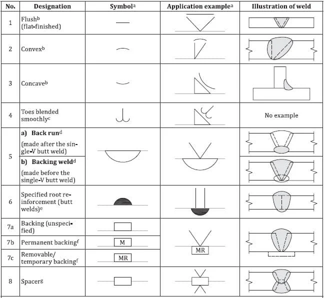
Supplementary Weld Symbols
Supplementary weld symbols are used in conjunction with elementary weld symbols to provide additional information. They complement the basic symbols and enhance the understanding of the welding requirements.
ISO-2553-supplementary-welding-symbols
Conclusion
Weld symbols in the UK are essential for effective communication between designers and welders in the field of sheet metal fabrication. Adhering to the EN ISO 2553:2013 standard ensures consistency and accuracy in the representation of welded joints.
By understanding the different components and meanings of weld symbols, professionals in the industry can interpret welding requirements correctly and achieve high-quality welds.


 + 7 Practical Examples")
