Flare Bevel Weld Symbol Explained (AWS A2.4, ISO & AS Standard) + 7 Practical Examples
Learn flare bevel weld symbols, types, size calculation, effective throat and AWS A2.4, ISO 2553 and AS 1101.3 Standards examples. Complete guide with drawings and comparison. Flare bevel welds are commonly used when welding rounded …
Learn flare bevel weld symbols, types, size calculation, effective throat and AWS A2.4, ISO 2553 and AS 1101.3 Standards examples. Complete guide with drawings and comparison.
Flare bevel welds are commonly used when welding rounded surfaces like pipes, tubes, or bars to flat plates or other curved members. Despite their frequent use in fabrication and structural work, many welders and inspectors struggle to correctly interpret the flare bevel weld symbol, size, and effective throat.
This complete guide explains everything you need—from AWS A2.4, ISO-2553 and AS 1101.3 Standards symbols to real-world examples and calculations.
In this blog post, we will explore the flare bevel groove weld, its size, callouts, strength, effective throat, and how it compares with a fillet weld.
What is a Flare Bevel Groove?
A flare bevel groove is a type of joint design used in welding where one of the joining pieces has a curved or rounded edge, such as in a pipe or tube. The other piece remains flat.
A flare bevel weld is a type of groove weld formed between a curved surface (like a pipe) and a flat or another curved surface, where the groove is naturally created by the shape of the base metal.
👉 Unlike standard groove welds, no machining is required—the joint geometry itself forms the groove.
📌 Key Characteristics:
Used for pipe-to-plate or pipe-to-pipe joints
Groove is curved (not straight)
Common in structural steel and piping fabrication
Defined under AWS welding symbols standard
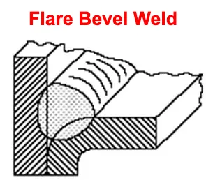
In simple words, A flare-bevel weld refers to a welding technique that joins a curved surface with a flat component. One typical example is the welding of a cylindrical bar to a plate, often used as a stop in mechanical parts. Additionally, flare bevel joints can be found in automotive panels and sheet applications, among other various uses.
Flare-bevel-weld
The weld is then applied at the intersection of the flat piece and the curved edge, creating a strong and secure joint. This type of weld is commonly used in instances where a rounded piece needs to be joined to a flat piece.
Types of Flare Bevel Weld
Flare bevel welds are a type of groove weld used in various welding applications. They are commonly used in structural steel fabrication, shipbuilding, and pipeline construction. Flare bevel welds are characterized by a sloping joint configuration that allows for a wider weld bead and increased weld penetration. Here are some common types of flare bevel welds:
This type of flare bevel weld involves a single bevel on one side of the joint. It is commonly used for joining plates of different thicknesses or when a single-sided weld is desired.
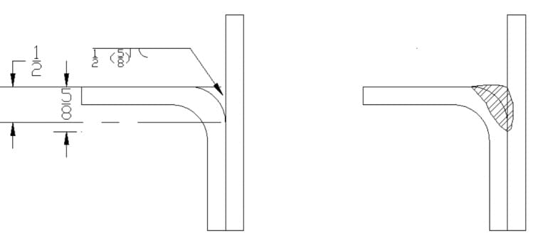
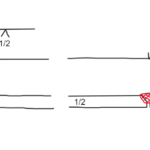
Below is an example of Single Flare Bevel weld with its symbol. The image shows a “flare” joint where a flat vertical plate is joined to the rounded corner (radius) of a bent horizontal plate. A complete Single Flare Bevel Welding Symbol elements are:
The symbol below the reference line tells the welder exactly how to fill that groove: Symbol Shape: The straight vertical line and curved arc indicate a Flare-Bevel-Groove. Position: Because the symbol is below the reference line, it indicates the weld should be made on the “Arrow Side” (the side where the arrow is pointing). 1/2 (Groove Size): The number to the left of the symbol indicates the Flare Groove Size (E). This is the intended depth of preparation. (5/8) (Depth of Prep): The number in parentheses indicates the Depth of Weld (S). In this case, the groove is1/2″ deep, but the engineer requires the weld to penetrate 5/8″ of that depth.
Flare Bevel Weld Symbol (A straight line and arc shape) placed on the reference line.
Weld size (Depth of flare bevel)- specified left of weld symbol, e.g. 5/8 (1/2) in below example.
Tail– If required to provide additional information.
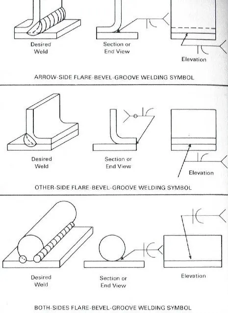
AWS A2.4 Double Flare Bevel Welding Symbol
A double flare bevel weld refers to a type of joint where both sides of a member are prepared with a flare bevel, while the other joining member is flat. This type of weld joint is commonly used in structural steel fabrication.
A double flare bevel weld symbol mirror the symbol of a single flare bevel weld symbol as shown in below example.
AWS A2.4 Single Flare V-Groove Welding Symbol
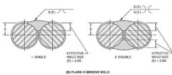
A single flare V-groove weld is a type of welding joint that involves creating a V-shaped groove on one side of the joint and a flat surface on the other side. This groove resembles the shape of a letter “V” and is used to facilitate the welding process. The single flare V-groove weld is commonly used in various applications, such as joining two metal plates together or connecting pipes.
Below is an example of Single Flare V-Groove Weld.
In below example, pic on left side shows a Single Flare V-Groove Weld and on right side is a Double Flare V-Groove Weld with welding symbols.
Double Flare V-Groove Weld with Symbol
A double flare V-groove weld is a welding joint that involves creating two V-shaped grooves on opposite sides of the joint (as shown in above figure- Right side welding symbol), forming a symmetrical “V” shape as shown in above example. This type of weld is commonly used when a stronger and more secure joint is required.
The double flare V-groove weld provides increased surface area for the weld, resulting in improved strength and stability. It is often used in applications where high structural integrity is necessary, such as in heavy machinery, pipelines, or structural steel fabrication.
Examples of AWS A2.4 Flare Groove welding Symbols
Below are various examples of Flare Bevel weld along with their symbols as per AWS A2.4 standard.
Flare Bevel Weld Size
The size of a flare bevel groove weld is determined by the depth of the groove on the curved piece. The size is typically specified in the welding symbol as a dimension, either in inches or millimeters, depending on the system of measurement being used.
The weld size is crucial as it determines the amount of filler material required for the weld, the heat input, and ultimately, the strength and durability of the weld.
Flare Bevel Weld Callout
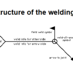
The flare bevel weld callout is represented by a standard welding symbol. The symbol includes a reference line, an arrow, and a tail. The symbol for the flare bevel weld is a straight line and a arc placed on the reference line’s .
The size is given on left side and length of the weld is given on the right side. Additional information, if specified, are indicated in the tail.
Flare Bevel Weld Strength
The strength of a flare bevel groove weld is determined by a number of factors. These include the quality of the welding process, the size of the weld, the type of filler material used, and the nature of the base materials being joined.
In general, a well-executed flare bevel weld can provide high strength and durability, making it suitable for applications where a strong joint between a flat and a curved piece is required.
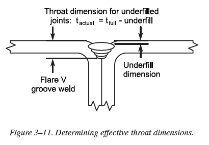
Flare Bevel Weld Effective Throat
The “effective throat” of a flare bevel weld refers to the shortest distance from the joint root to the face of the weld. This dimension is critical as it directly influences the strength and quality of the weld.
The effective throat of a flare bevel weld will vary based on the size and angle of the bevel, as well as the skill of the welder. It is something that needs to be closely monitored during the welding process to ensure the joint’s integrity.
While both flare bevel welds and fillet welds are used to join two pieces of material, they differ in terms of their design, application, and symbol representation.
As we’ve discussed, a flare bevel groove weld is used when one of the joining pieces has a rounded edge, such as a pipe or tube, while the other piece is flat. On the other hand, a fillet weld is used to join two pieces at a right angle, forming a corner.
In terms of welding symbols, a fillet weld is represented by a right triangle on the reference line, while the flare bevel weld symbol is a combination of a straight and a arc.
Weld Type
Flare Bevel Weld
Fillet Weld
Joint Configuration
Weld between a curved surface and a flat part
Weld between two intersecting surfaces, typically at a right angle
Shape of Weld
Flare bevel joint, with a radius and a flat part
Triangular or curved shape, resembling a fillet
Strength
Provides good strength and load-bearing capacity
Provides moderate strength, depending on the size and length of the weld
Applications
Commonly used for joining round bars to flat plates, automotive panels, and sheet applications
Widely used in various industries for joining structural components, frames, and brackets
Welding Technique
Requires preparation of a beveled edge on one side of the joint
Involves depositing filler material along the joint intersection
Visual Appearance
Results in a smooth and continuous transition between the curved and flat surfaces
Creates a visible triangular or curved fillet at the joint
Welding Difficulty
Requires precise beveling and alignment of the joint
Relatively easier to perform, especially for beginners
Welding Positions
Can be performed in various positions, including flat, horizontal, vertical, and overhead
Can be performed in various positions, but certain positions may require additional support or positioning techniques
Strength of Connection
Provides a strong and rigid connection, suitable for heavy-duty applications
Offers sufficient strength for many applications, but may not be as strong as a flare bevel weld
Visual Inspection
Requires careful inspection to ensure proper fusion and penetration along the beveled edges
Requires inspection to ensure proper fusion and adequate throat thickness of the fillet weld
Non-Destructive Testing
May require additional testing methods, such as radiographic or ultrasonic testing, to ensure weld quality
May require additional testing methods, such as visual inspection or dye penetrant testing, to ensure weld quality
The choice between a flare bevel weld and a fillet weld depends on the specific requirements of the project, including the design of the pieces being joined and the strength required for the weld.
In conclusion, understanding the intricacies of the flare bevel groove weld, its symbol, and how it compares with other types of welds is critical for anyone in the welding industry. This knowledge ensures proper communication, execution, and quality control in welding practices, leading to safer and more efficient operations.
Dr. Kumar is a PhD-qualified Welding and Materials Expert with a career spanning 18+ years across metallurgy and NDT. A triple-threat in the industry, he is an IWE, AWS-CWI, and ASNT NDT Level III certified professional. Dr. Kumar is the author of several leading technical resources and is a premier specialist in welding symbol instruction, dedicated to improving global standards in welding engineering and inspection.
Dr. Kumar is a PhD-qualified Welding and Materials Expert with a career spanning 18+ years across metallurgy and NDT. A triple-threat in the industry, he is an IWE, AWS-CWI, and ASNT NDT Level III certified professional. Dr. Kumar is the author of several leading technical resources and is a premier specialist in welding symbol instruction, dedicated to improving global standards in welding engineering and inspection.


: A Comprehensive Guide")


