Understanding Welding Symbols on Drawing: An In-Depth Guide
Welding Symbols Welding is a complex trade that requires a unique set of skills and knowledge. One crucial aspect of this field that often goes overlooked by those outside of it is the importance of welding …
Welding is a complex trade that requires a unique set of skills and knowledge. One crucial aspect of this field that often goes overlooked by those outside of it is the importance of welding symbols. These symbols, which are used in blueprints and plans, communicate essential information about the weld to be made. This includes details about the type of weld, its size, its location, and more.
In this in-depth guide, we’ll take a close look at different types of welding symbols and what they mean. By the end, you’ll have a comprehensive understanding of these essential tools in the welding trade.
Importance of Welding Symbols on Drawing
Some people think you don’t always need to tell welders exactly where and how to weld on the plans. They say we should just trust the welder to do a good job. But this can be very risky. The kind of welding and its size need to match the main material and how the finished product will be used. Usually, only the design office has all this information.
If the design office doesn’t carefully explain how the welding should be done, big problems can happen. This is especially true when the job is given to someone outside the company. In these cases, the instructions need to be very clear.
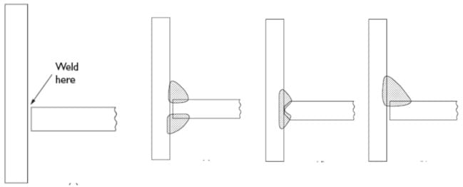
You don’t often see “weld here” on a blueprint. This is because it’s too vague and can mean different things to different people. Welding involves more than just where to weld; it also involves how to weld, what type of weld to use, and so on. Just saying “weld here” can lead to confusion and mistakes.
Advantages of Welding Symbols
Using welding symbols to indicate necessary welding information on engineering drawings offers several advantages:
Efficiency: The use of symbols can significantly reduce the time needed to complete a drawing compared to drawing the weld as it will appear.
Clarity: Welding symbols are standardized and universally understood in the industry, ensuring clear communication and minimizing confusion or misinterpretation.
Compactness: Symbols take up less space on the drawing, keeping it uncluttered and easy to read.
Detail: Symbols can convey a lot of information, such as the type of weld, size, location, length, and other specifics, in a compact form.
Consistency: Since the symbols are standardized, they provide consistency across different drawings, irrespective of who the designer or the welder is.
Precision: They allow precise communication of the exact requirements of the weld, reducing the chances of errors and ensuring the quality of the final product.
Difference between Weld Symbol and Welding Symbols
Weld Symbol: This refers to the specific symbol used to denote the type of weld that needs to be executed. For example, a ‘V’ could indicate a single-V weld, a ‘U’ might represent a single-U weld, and a triangle could symbolize a fillet weld. The weld symbol alone does not contain any additional information about the welding process, such as the weld size, length, specific welding process, non-destructive testing requirements, and so on.
Welding Symbol: This is a more comprehensive term than the weld symbol. It includes the weld symbol as well as supplementary information that is necessary for the execution of the weld. This supplementary information is typically conveyed through a reference line, to which the weld symbols can be appended, and an arrow line, which points to the location of the welded joint on the workpiece. The welding symbol can also include additional elements like the weld sizes and lengths, welding process, non-destructive testing requirements, and more.
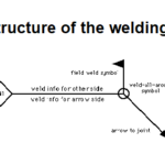
The Structure of Welding Symbols
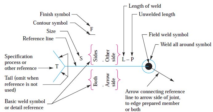
Before we delve into specific welding symbols, it’s important to understand the structure of a welding symbol. A complete welding symbol is made up of the following eight elements:
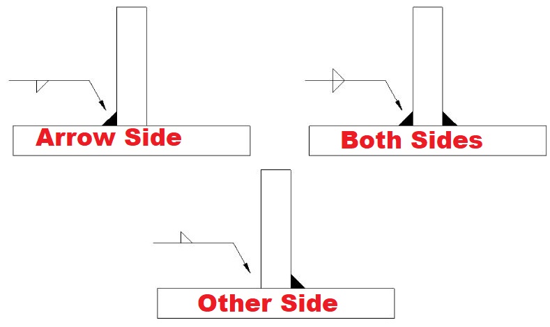
The reference line: This is one of the primary elements of the welding symbol.
The arrow: This points to the location where the weld should be applied.
The tail: This is used to provide additional instructions or information.
The basic weld symbol: This indicates the type of weld to be executed.
Dimensions and other data: This provides details such as the size and length of the weld.
Supplementary symbols: These provide further information about the weld, such as whether it requires contouring or surface finishing.
Finish symbols: Also called Contour Symbols. These denote the type of finish required for the weld, such as chipping or grinding.
Specification, process or other references: These provide additional instructions related to the welding process, such as the specific welding method to be used or any specification that needs to be adhered to.
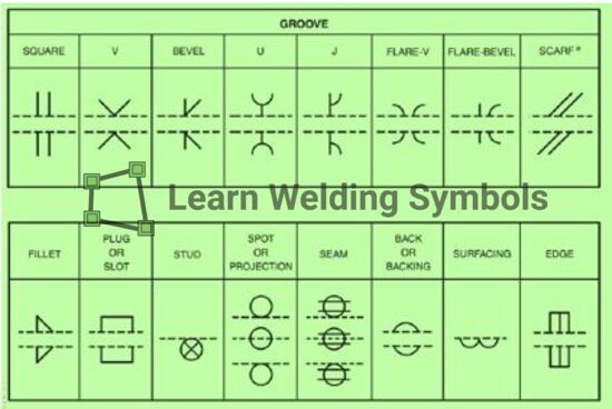
Basic or Primary Weld Symbols
Primary or basic welding symbols are graphical representations used to communicate the type of weld that a welder should perform on a workpiece. The following are total 16 nos. basic welding symbols:
The most commonly used Basic weld Symbol are listed below. Check out this post for in depth learning about Basic Weld Symbols.
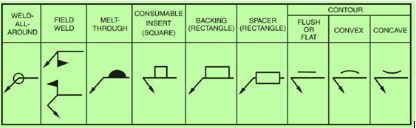
Supplementary welding symbols are used in conjunction with basic welding symbols to provide additional information about the weld. Here are the main 9 nos. supplementary symbols:
Weld All Around Symbol: This is a supplementary symbol used to indicate that the weld should be continuous around a joint. It is typically used when the joint is a ring or a closed figure. The symbol is represented by a small circle placed at the intersection where the end of the reference line meets the arrow.
Field Weld Symbol: A field weld refers to a weld that is made at a location other than a shop, such as a construction site. The field weld symbol consists of a flag that appears on the reference line. The flag points to the right if the reference line is horizontal, or it points upward if the reference line is vertical.
Convex Contour Symbol: This symbol tells the welder that the face of the weld should be convex (curved outward). It is represented by a horizontal line that curves upward.
Concave Contour Symbol: It indicates that the face of the weld should be concave (curved inward). It is represented by a horizontal line that curves downward.
Flat Contour Symbol: This symbol indicates that the face of the weld should be flat. It is represented by a straight horizontal line.
Melt-Through Symbol: This symbol signifies that complete joint penetration is to be achieved in a single-sided butt weld. It is represented by a filled-in semi circle on the reference line.
Backing Bar Symbol: This symbol notifies that a backing bar should be used for the weld. It’s represented by a rectangle above the reference line.
Flush Contour Symbol: This symbol indicates that the weld should be flush with the workpiece surface. It is represented by a straight line parallel to the reference line.
Consumable Insert Symbol: This symbol indicates the use of a consumable insert for the weld. It’s represented by a “Square” shape.
Now that we’ve covered the basic structure of welding symbols, let’s look at some of the specific symbols and what they mean.
1. Fillet Weld
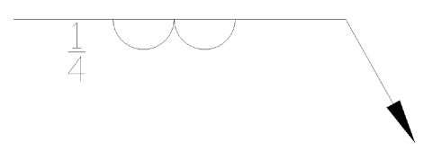
A fillet weld is used to fill in the interior angle between two pieces of material. The symbol for a fillet weld is a right triangle, which can be oriented in different ways depending on the specifics of the weld.
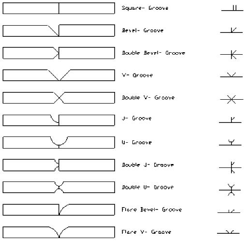
2. Groove Weld
Groove welds are made in the groove between two pieces of material. There are many different types of groove welds, including square groove welds, V-groove welds, bevel groove welds, U-groove welds, J-groove welds, and flange welds. Each of these has its own unique symbol, which is a variation on a square or a triangle shape.
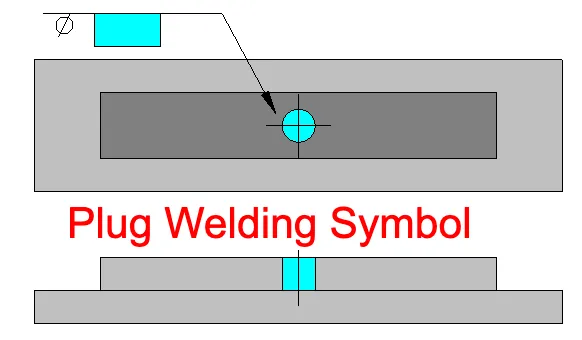
3. Plug or Slot Weld
Plug welds are circular welds created within an existing hole, typically in one piece of metal, to join it to another piece. The symbol for a plug weld is a rectangle, with the diameter symbol and corresponding numerical value denoted on the left side of the symbol.
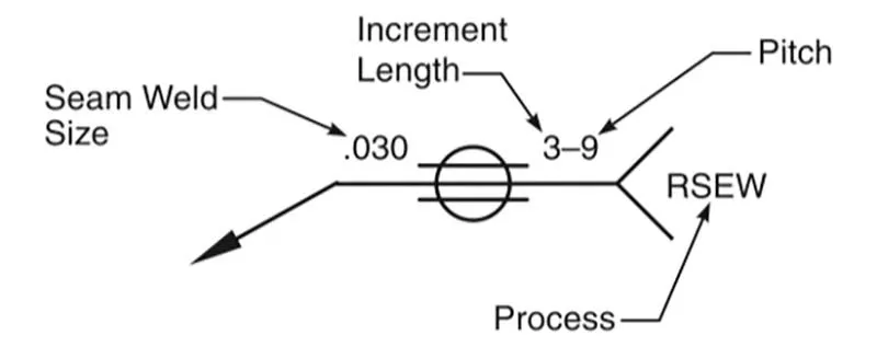
4. Seam Weld
A seam weld is used to join two pieces of material along a continuous line. The symbol for a seam weld is two parallel lines placed across a circle.
5. Spot or Projection Weld
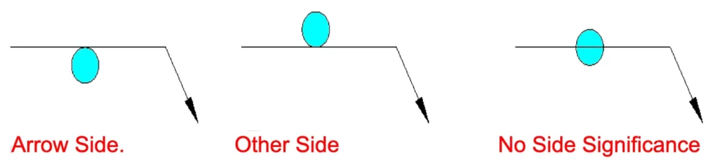
The spot weld symbol is represented by a straightforward circle, which can be positioned above, below, or directly on the reference line. Centering the symbol on the reference line signifies that there is no specific side importance. This non-side-specific application is frequently done with a resistance spot welder, a tool commonly used in sheet metal work.
A spot weld is essentially a weld applied on one component’s surface with sufficient heat to melt into the material forming the mating surface. This process is carried out without any prior preparation of the parts involved.
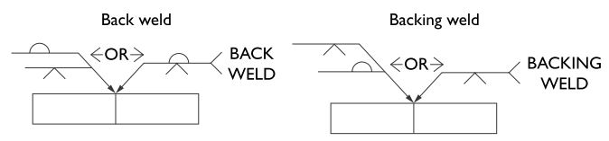
6. Back or Backing Weld
A back or backing weld is used to provide support for a primary weld, often a groove weld. The symbol for a back or backing weld is a semi-circle.
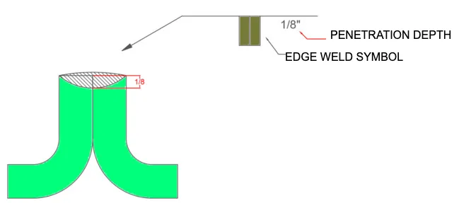
The edge welding symbol is used in welding to indicate that two pieces of metal will be joined by a weld along their edges. It is typically represented by two rectangles placed on the reference line. The supplementary weld symbol (e.g., contour) if required, is placed on the edge weld symbol and includes additional information such as the weld size, length, and spacing.
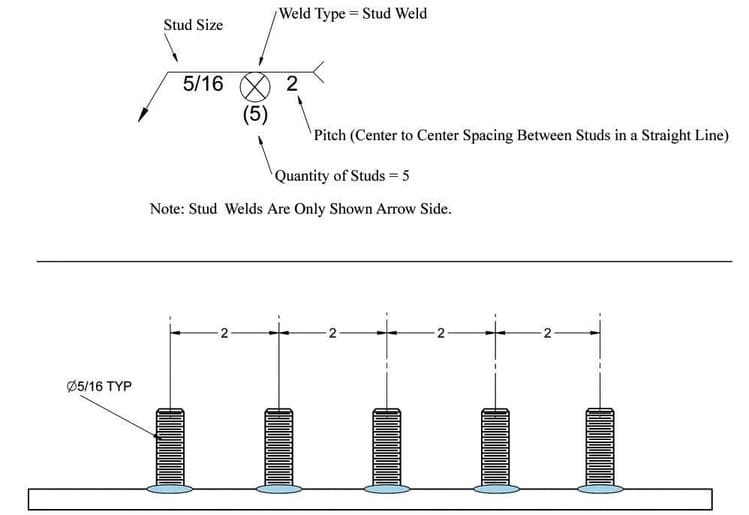
9. Stud Weld Symbol
A stud weld symbol in welding symbology is represented by a circle. This circle is placed on the reference line that is perpendicular to the joint. Here’s a simplified representation:
The circle represents a stud weld. The tail of the welding symbol is where supplementary information may be provided.
Additionally, the size, quantity, or spacing of the studs would be written to the left of the symbol, while the length of the stud (pitch) would be written to the right of the symbol, on the reference line.
Conclusion
Understanding welding symbols is essential for anyone involved in welding, whether as a welder, a designer, or an inspector. These symbols communicate vital information about how a welding job is to be carried out, ensuring that the end result is safe, reliable, and up to standard. By familiarizing yourself with the symbols outlined in this guide, you’ll be well on your way to mastering this important aspect of the welding trade.
Dr. Kumar is a PhD-qualified Welding and Materials Expert with a career spanning 18+ years across metallurgy and NDT. A triple-threat in the industry, he is an IWE, AWS-CWI, and ASNT NDT Level III certified professional. Dr. Kumar is the author of several leading technical resources and is a premier specialist in welding symbol instruction, dedicated to improving global standards in welding engineering and inspection.
Dr. Kumar is a PhD-qualified Welding and Materials Expert with a career spanning 18+ years across metallurgy and NDT. A triple-threat in the industry, he is an IWE, AWS-CWI, and ASNT NDT Level III certified professional. Dr. Kumar is the author of several leading technical resources and is a premier specialist in welding symbol instruction, dedicated to improving global standards in welding engineering and inspection.