Parts of a Welding Symbol Welding symbols are crucial in communicating the specifics of a welding job. Each symbol consists of two fundamental parts: In addition to these basic parts, some welding symbols incorporate a third component: …
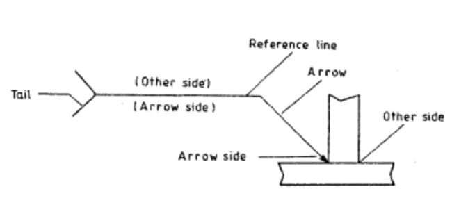
Reference Line: This component is always horizontal and serves as the basis of the welding symbol.
Arrow: The arrow, always inclined to the reference line at one end, points to the exact location on the drawing where the weld is to be executed.
In addition to these basic parts, some welding symbols incorporate a third component:
Tail: The tail is used to specify the welding and cutting process, along with any welding specifications, procedures, or supplementary information necessary for performing the weld. However, the tail can be omitted if there’s no need to reference these details.
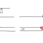
The reference line in a welding symbol has two distinct sides:
Other Side: This refers to the area above the reference line.
Arrow Side: This refers to the area below the reference line.
Understanding these components and their positions is key to correctly interpreting and executing the instructions conveyed by welding symbols.
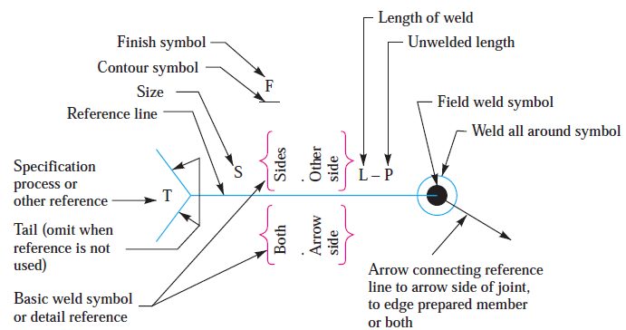
Welding symbols are composed of a reference line, arrow, and tail, with various elements added to convey specific information. while the reference line and arrow are the fundamental components of a welding symbol, it can incorporate up to eight elements to convey more detailed information. Including the basic two, these elements are:
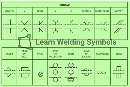
Here’s a brief overview of common welding symbols and their meanings:
Welding Symbol Parts
Reference line: The horizontal line that forms the foundation of the welding symbol. All other elements are attached to or placed around this line.
Arrow: A line with an arrowhead that points to the joint or location where the weld is required. The arrow can be at any angle, but it is usually horizontal or diagonal.
Tail: A line extending from the end of the reference line opposite the arrow. The tail is optional and is used to include supplementary information, such as welding process, welding sequence, or other notes.
Weld symbols: These are placed either above or below the reference line to indicate the type of weld required. Some common weld symbols include:
Fillet weld: A triangular symbol representing a weld with a triangular cross-section, used to join two surfaces at right angles.Groove weld: A symbol representing a weld made in a groove between two workpieces to be joined. There are several types of groove welds, each with their own specific symbol (e.g., V-groove, U-groove, J-groove).Plug or slot weld: A symbol representing a weld made in a hole or slot in one workpiece that joins it to another workpiece.
Spot or projection weld: A symbol representing a weld made at specific points or projections on the workpiece, typically used in resistance welding.
Weld dimensions: Numerical values placed around the weld symbol to indicate the size of the weld, such as the leg length, throat, or depth of penetration.
Welding process and other information: Letters or abbreviations placed in the tail of the welding symbol to indicate the welding process (e.g., GMAW for gas metal arc welding) or other supplementary information.
Welding location: Symbols placed around the reference line and arrow to indicate the location of the weld, such as whether it should be on the arrow side, other side, or both sides of the joint.
Contour and finishing: Symbols placed near the weld symbol to indicate the desired weld contour (e.g., flush or convex) and the method of finishing (e.g., grinding or chipping).
Multiple welds: Symbols and numerals used to indicate that a weld should be performed multiple times, in a specific sequence, or with a specific spacing.
Understanding welding symbols is crucial for welders, engineers, and other professionals involved in the design, fabrication, and inspection of welded structures. Familiarity with these symbols helps ensure that the correct welding procedures are followed and that the final product meets the desired specifications.
Dr. Kumar is a PhD-qualified Welding and Materials Expert with a career spanning 18+ years across metallurgy and NDT. A triple-threat in the industry, he is an IWE, AWS-CWI, and ASNT NDT Level III certified professional. Dr. Kumar is the author of several leading technical resources and is a premier specialist in welding symbol instruction, dedicated to improving global standards in welding engineering and inspection.
Dr. Kumar is a PhD-qualified Welding and Materials Expert with a career spanning 18+ years across metallurgy and NDT. A triple-threat in the industry, he is an IWE, AWS-CWI, and ASNT NDT Level III certified professional. Dr. Kumar is the author of several leading technical resources and is a premier specialist in welding symbol instruction, dedicated to improving global standards in welding engineering and inspection.