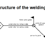
What is Weld Symbols? Weld symbols are a standardized set of symbols used on engineering drawings to indicate the specific weld used. They provide information on the type of weld, its size, placement and other details. Main …
Weld symbols are a standardized set of symbols used on engineering drawings to indicate the specific weld used. They provide information on the type of weld, its size, placement and other details.
Various other symbols and annotations are used to indicate the type of weld, weld size, weld preparation, weld finishing, and other important information related to welding. For example, a symbol that looks like a triangle above the reference line indicates that the weld should have a fillet weld shape, while a symbol that looks like a triangle indicates that the weld should have a V-groove shape.
Weld Symbols are classified as:
Primary Weld Symbols, &
Supplementary or Secondary Weld Symbols.
Primary Weld Symbols
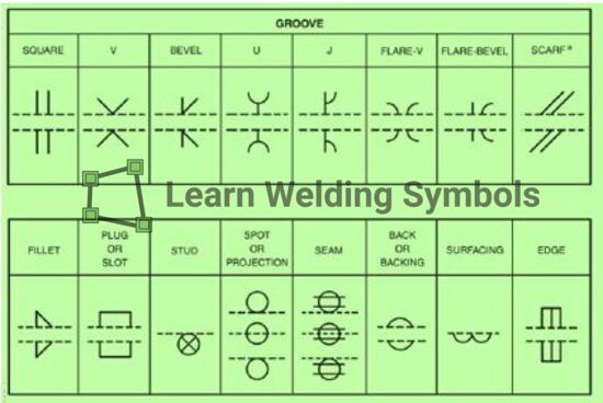
There are total 16 Primary Weld Symbols as per AWS A2.4 specification as shown in the below picture.
The most common types of welds represented by weld symbols are:
Groove welds: Groove welds are used to join plates with different thicknesses. The common groove weld symbols are:
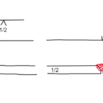
Square groove weld:For welding plates of the same thickness. Denoted by an unfilled arrow.
V-groove weld: For welding plates of unequal thickness. Represented by a filled arrow.
U-groove weld:For welding curved plates. Symbolized by a filled arrow with curved end.
J-groove weld: For welding plates where one plate extends over the other. Indicated by a filled arrow with extended end.
Fillet welds: Used to join two surfaces at right angles. Represented by a triangle symbol. The dimensions of the triangle specify the size of the fillet weld.
Plug and Slot welds: Circular and elongated welds respectively, used to join overlapping surfaces.
Seam weld: Long weld joining lapped or offset edges.
Backing weld: Weld made to the backside of a groove weld or fillet weld. Provides reinforcement.
Supplementary or Secondary Weld Symbols
Weld symbols are used to communicate important information about welding on a drawing or blueprint. They provide details about the type of weld, its location, size, and other important information.
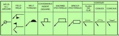
However, in some cases, the basic weld symbol may not provide all the necessary information for the weld. In such cases, supplementary or secondary weld symbols are used to supplement the basic symbol and provide additional information. Let’s take a closer look at some examples of 9 main supplementary weld symbols and their meanings.
Weld all around (WAA)The weld all around symbol indicates that the weld should be continuous around the entire perimeter of the joint. This symbol is commonly used for circular or cylindrical joints, where a continuous weld is required to ensure strength and durability. The WAA symbol is depicted as a circle around the basic weld symbol.
Field weld (FW) The field weld symbol indicates that the weld is to be performed on-site rather than in a shop or factory. This symbol is commonly used in construction or infrastructure projects where large, heavy components are welded together on-site. The FW symbol is depicted as an flag pointing vertical at the junction of reference line & arrow line.
Melt-through (MT) The melt-through symbol indicates that the weld should penetrate completely through the workpiece. This symbol is commonly used for thicker materials where a complete penetration weld is required for strength and durability. The MT symbol is depicted as a dark half-circle above the reference line.
Consumable insert (CI) The consumable insert symbol indicates that a specific type of filler material or electrode should be used in the welding process. This symbol is commonly used when welding dissimilar metals or when a specific type of weld is required for strength or durability.
Contour Weld symbols The contour symbol indicates that the weld should have a specific shape or contour, as specified on the drawing or blueprint. This symbol is commonly used when welding curved or irregular surfaces, where the shape of the weld is critical for strength or durability.
In summary, weld symbols are a concise way to convey the welding requirements to shop personnel involved in fabrication and welding. Familiarity with these standard symbols allows for clear communication and interpretation of weld specifications in engineering drawings. Let me know if you would like me to elaborate on any part of this article in comment section.
Dr. Kumar is a PhD-qualified Welding and Materials Expert with a career spanning 18+ years across metallurgy and NDT. A triple-threat in the industry, he is an IWE, AWS-CWI, and ASNT NDT Level III certified professional. Dr. Kumar is the author of several leading technical resources and is a premier specialist in welding symbol instruction, dedicated to improving global standards in welding engineering and inspection.
Dr. Kumar is a PhD-qualified Welding and Materials Expert with a career spanning 18+ years across metallurgy and NDT. A triple-threat in the industry, he is an IWE, AWS-CWI, and ASNT NDT Level III certified professional. Dr. Kumar is the author of several leading technical resources and is a premier specialist in welding symbol instruction, dedicated to improving global standards in welding engineering and inspection.


 + 7 Practical Examples")

