What is a Welding Symbol? See also Double Fillet Weld Symbol What is a Welding Symbol? If you have ever looked at a structural blueprint or a fabrication drawing, you have likely noticed a series …
If you have ever looked at a structural blueprint or a fabrication drawing, you have likely noticed a series of lines, arrows, and geometric shapes pointing to various joints. To the untrained eye, it looks like a secret code. In reality, it is the universal language of welding.
Understanding this language is crucial for ensuring that a metal structure is built exactly as the engineer intended. Let’s break down the basics of what a welding symbol actually is, based on standard guidelines.
So, what does a Welding Symbol actually mean?
📐
The Definition
Hover or Tap
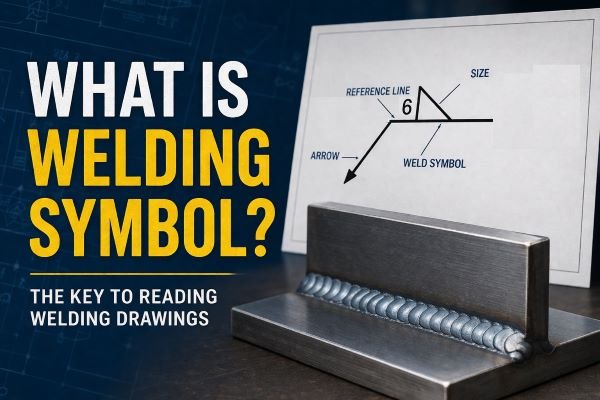
A welding symbol is a graphical representation used to communicate precise information about the type and location of welds directly on an engineering drawing or blueprint.
🏭
Industry Application
Hover or Tap
Welding symbols are heavily utilized across major industries such as construction, manufacturing, and structural engineering, anywhere welding is required to safely join metal parts together.
🔍
Core Anatomy
Hover or Tap
They typically consist of a reference line (which represents the edge of the joint to be welded), combined with various symbols and annotations that provide data about the weld’s type, location, and required finish.
“Weld Symbol” vs. “Welding Symbol”
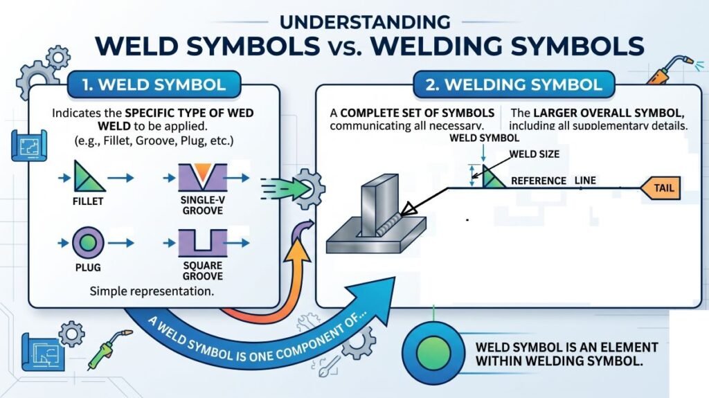
Many people use the terms interchangeably, but as defined in AWS A3.0M/A3.0, there is a specific distinction between the terms “weld symbol” and “welding symbol”.
The Weld Symbol: This specifically indicates the actual type of weld to be applied.
The Welding Symbol: The weld symbol, when it is used, is merely one component of the larger, overall welding symbol.
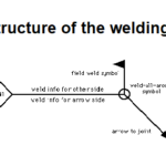
Core Anatomy of the Symbol
A complete welding symbol may consist of several different elements to convey specific instructions. However, at its core, there are only two elements that are absolutely required:
A horizontal reference line (Blue Line is below example)
An arrow
Parts of a Welding Symbol
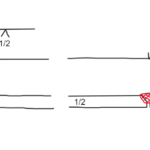
In this system, the physical joint is used as the basis of reference. The placement of the arrow dictates how the welder interprets the instructions:
Arrow Side: This is the side of the joint to which the arrow of the welding symbol directly points.
Other Side: This is simply the side of the joint that is opposite the arrow side.
When specific weld symbols (like a triangle for a fillet weld) are included to specify the weld type, they must be drawn in direct contact with the reference line.
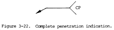
The Tail: Adding Specific Details
Sometimes, the basic reference line and arrow aren’t enough to convey all the necessary instructions. In these cases, the symbol will include a “tail” as shown in below example.
CP-weld-symbol
Decoding Welding Symbols
The universal language of fabrication and engineering
The Symbol Tail & Extra Data
The tail of the symbol is used for designating additional information necessary for making the weld or braze. This can include:
Specifications or the required welding process.
The required strength for certain welds.
Identification of the specific filler metal or electrode to be used.
Secondary operations like peening or backgouging.
It is worth noting that this extra information doesn’t have to live in the tail. Alternatively, welding information can be conveyed through other means, such as drawing details, notes, specifications, codes, or standards. When information is provided elsewhere, it eliminates the need to clutter the welding symbol with those corresponding elements.
Placement and Supplementary Information
While a welding symbol can contain many different elements, all elements used must have specific, standardized locations within the symbol. However, these mandatory location requirements should not be interpreted as a necessity to include every possible element in every single welding symbol.
Additionally, supplementary symbols can be used in connection with standard welding symbols to convey even more complex instructions.
Ultimately, the placement of the entire symbol is critical. To avoid any confusion on the shop floor, the arrow of the welding symbol must point to a line, area, or location that conclusively identifies the exact joint or area to be welded.
Hover over the cards below to see some of the most common symbols used on blueprints:
Fillet Weld Symbol
Represents a weld that joins two pieces of metal at a right angle, forming a triangular cross-section.
Groove Weld Symbol
Represents a weld that joins two pieces of metal along a groove or channel in the edge of the joint.
Spot Weld Symbol
Represents a series of small welds used to join two pieces of metal at specific locations.
Why Welding Symbols Matter
Welding Symbols Meaning:
Welding symbols are a standardized system of symbols used to communicate welding requirements on engineering drawings. They provide information about the type, size, and location of welds, as well as any additional information needed to complete the welding process.
Importance in Fabrication:
Welding symbols are important because they allow engineers, fabricators, and welders to communicate effectively about the welding requirements for a particular project. They help to ensure that the welds are properly placed, sized, and finished, and that the resulting structure or component meets the required specifications.
Frequently Asked Questions (FAQ)
Understanding AWS Basic Welding Symbols
What is the exact difference between a “weld symbol” and a “welding symbol”?
As defined in AWS A3.0M/A3.0, there is a clear distinction between the two terms. A weld symbol is a specific graphic character connected to the reference line that specifies the joint geometry or the type of weld. A welding symbol is the complete graphical representation of the specifications for producing a welded joint. The weld symbol, when used, is simply one part of the overall welding symbol.
What are the strictly required elements of a welding symbol?
While a welding symbol may consist of several different elements to convey specific information, only a horizontal reference line and the arrow are actually required elements.
How do the “arrow side” and “other side” work?
In the present AWS system, the joint itself is the basis of reference. The “arrow side” is defined as the side of the joint to which the arrow of the welding symbol points. The “other side” is simply the side of the joint opposite the arrow side.
Where exactly must the weld symbol and arrow be placed?
When using weld symbols, they must be drawn in direct contact with the reference line. Furthermore, the arrow of the welding symbol must point to a line, location, or area that conclusively identifies the exact joint, location, or area to be welded.
What information goes into the “tail” of the symbol?
The tail of the symbol is used for designating additional information necessary for making the weld or braze. This extra information can include a specification, the required process, the strength for certain welds, identification of the filler metal or electrode, or other secondary operations like peening and backgouging.
Do I have to include every element in my welding symbol?
No. All elements, when used, have specific mandatory locations within the welding symbol, but this should not be interpreted as a necessity to include the element in every welding symbol. Alternatively, welding information can be conveyed by other means, such as drawing notes, specifications, codes, or other drawings, which eliminates the need to clutter the welding symbol with those corresponding elements.
What are supplementary symbols and examination method designations?
A supplementary symbol is a graphic character incorporated into a symbol for welding, brazing, or nondestructive examination to communicate additional requirements. An examination method designation is a specific letter designation incorporated into a symbol for nondestructive examination to specify the exact examination method.
Dr. Kumar is a PhD-qualified Welding and Materials Expert with a career spanning 18+ years across metallurgy and NDT. A triple-threat in the industry, he is an IWE, AWS-CWI, and ASNT NDT Level III certified professional. Dr. Kumar is the author of several leading technical resources and is a premier specialist in welding symbol instruction, dedicated to improving global standards in welding engineering and inspection.
Dr. Kumar is a PhD-qualified Welding and Materials Expert with a career spanning 18+ years across metallurgy and NDT. A triple-threat in the industry, he is an IWE, AWS-CWI, and ASNT NDT Level III certified professional. Dr. Kumar is the author of several leading technical resources and is a premier specialist in welding symbol instruction, dedicated to improving global standards in welding engineering and inspection.