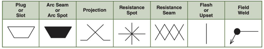
Flash and Upset Welding Symbols Welding symbols are graphical representations used to communicate vital information about welds in technical drawings and blueprints. They serve as a common language between designers, engineers, and welders, ensuring clear …
Welding symbols are graphical representations used to communicate vital information about welds in technical drawings and blueprints. They serve as a common language between designers, engineers, and welders, ensuring clear and precise instructions for welding operations.
In this blog post, I have covered about Basics of welding symbols, Flash and Upset Welding Symbol.
What is a Flash Weld?
The name “flash welding” comes from the flashing phenomenon that occurs during the process. Initially, a small gap is intentionally left between the workpieces to allow for the formation of an arc. When the electrical current is applied, an arc is struck across the gap, creating a bright flash of light. This flash signifies the initiation of the welding process.
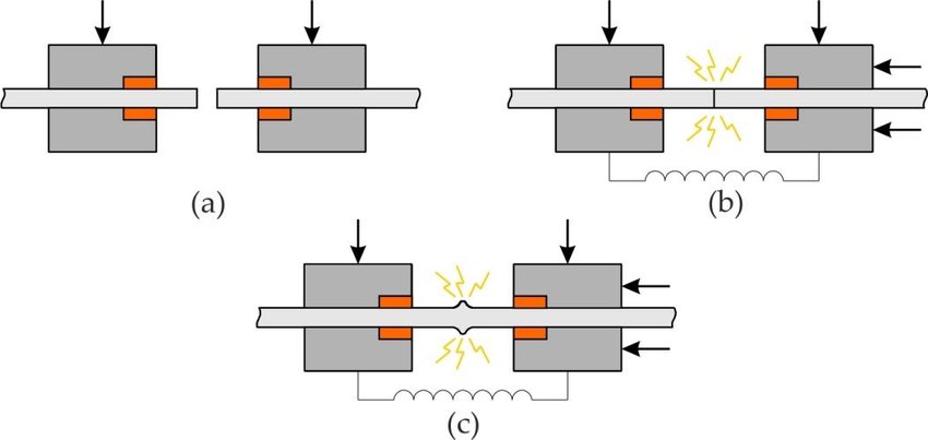
Flash welding is a solid-state welding process used to join two metal workpieces. It is a type of resistance welding where the heat for welding is generated by the resistance to electric current flow at the interface between the workpieces. Flash welding is typically used for joining similar or dissimilar metals with large cross-sectional areas.
In flash welding, the workpieces are clamped together and a high electrical current is passed through them. The current flows through the interface between the workpieces, creating intense heat due to resistance. As the heat builds up, the metal at the interface reaches its melting point and forms a molten pool. At this stage, a high-pressure force is applied to forge the workpieces together, creating a solid-state weld.
What is Upset Weld?
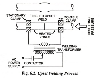
An upset weld is a solid-state welding technique used to join two metal workpieces by creating a mechanical bond rather than relying on melting and fusion. It is commonly used for joining similar or dissimilar metals with small cross-sectional areas.
In an upset weld, the two workpieces to be joined are brought into contact and held under pressure. Mechanical force is then applied to the workpieces, typically through compression or impact, causing localized deformation and plastic flow of the metal. This deformation disrupts the surface oxides and contaminants, allowing clean metal surfaces to come into contact. The resulting contact area forms a metallurgical bond, creating a strong joint.
The term “upset” in upset welding refers to the deformation of the workpieces during the welding process. The metal is compressed and displaced, causing it to bulge or “upset” at the joint interface. This plastic deformation increases the contact area and enhances the strength of the joint.
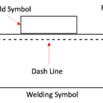
Reference Line: The Foundation of Welding Symbols
The reference line forms the basis of a welding symbol, acting as a key point of orientation for all other elements. It provides a frame of reference for the symbol and establishes the relationship between different components. At one end of the reference line, an arrow is affixed to indicate the specific side of the joint. If necessary, a tail may be added on the opposite end to accommodate specifications or other references.
Arrow: Directing Welding Information
The arrow in a welding symbol connects the reference line to a designated side of the joint, providing crucial information about the welding process. Depending on the type of welding symbol used, the arrow side represents the side of the joint where welding occurs, while the opposite side is known as the other side. Different arrow orientations communicate specific instructions, such as chamfering for bevel and J-groove weld symbols.
Basic weld symbols play a vital role in identifying the type of welding technique to be employed. Positioned near the center of the reference line, these symbols are placed above, below, or on both sides of the line. Weld symbols on the arrow side of the joint are located on the lower side of the reference line, while those pertaining to the other side are placed on the upper side.
Supplementary Symbols: Enhancing Welding Information
Supplementary symbols provide additional information about the welding process, including the extent of welding, location, and contour of the weld bead. Symbols such as “weld-all-around” and “field” offer crucial details, ensuring precise execution of the weld. These symbols are placed at the end of the reference line, near the base of the arrow, as depicted in the Supplementary Weld Symbols table.
Dimensions in welding symbols encompass various measurements, such as weld size, length, spacing, and other relevant details. The size of the weld is indicated to the left of the basic weld symbol, while the length is denoted on the right. Additional information, such as groove angles and the number of spot or projection welds, is located above or below the symbol. Enclosed within parentheses, the number of spot or projection welds clarifies the specific quantity required.
Contour and Finish Symbols: Shaping the Weld
Contour symbols represent the shape or contour of the weld, while finish symbols indicate the desired method of finishing. Placed above or below the weld symbol, these elements provide essential instructions for achieving the desired weld shape and surface finish. Examples of finish symbols include “C” for chipping, “G” for grinding, “M” for machining, “R” for rolling, and “H” for hammering.
Tail: Additional Specifications and References
The tail, positioned at the end of the reference line opposite the arrow, is used to incorporate specifications, processes, or other relevant references in the welding symbol. When no specific reference is necessary, the tail may be omitted. Including a tail ensures that all essential information is captured within the welding symbol, promoting clarity and eliminating ambiguity.
Flash Welding Symbols
Flash welding, also known as percussion welding, was a commonly used welding technique in the past. Flash welding symbols were employed to represent this specific welding process on engineering drawings. These symbols consisted of unique graphical elements that conveyed essential information about the welding operation.
Upset Welding Symbols
Similar to flash welding, upset welding was another widely used welding method. Upset welding symbols were utilized to indicate this particular welding technique on welding drawings. These symbols provided valuable details regarding the welding procedure and requirements.
Flash and Upset Welding Symbols
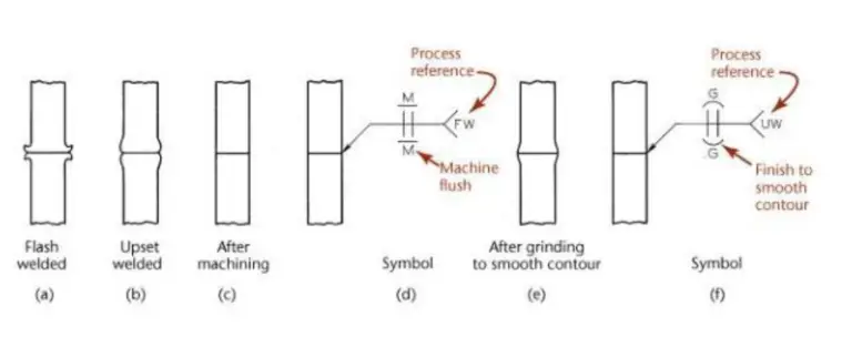
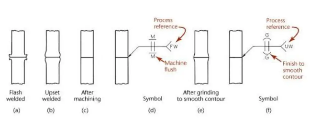
Flash and upset welding symbols have been discontinued in AWS A2.4 2020 edition and are no longer supported in current welding practices.
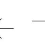
Instead, if a welding symbol is required to represent flash or upset welding, it is recommended to use a reference line and arrow. In the tail of the welding symbol, either “FW” or “UW” can be designated to indicate flash welding or upset welding, respectively. This updated approach ensures clarity and conformity in welding drawings and specifications.
In a drawing, if tails show any of the following designation, it refer to these specific weld types:
FW- Flash Welding
UW upset welding
UW-HF high-frequency upset welding
UW-I induction upset welding
Nonpreferred weld symbols were used in older versions of welding standards but are no longer considered standard in current versions. However, it is possible to encounter these nonpreferred symbols on older prints or drawings that were created before the adoption of the updated standards.
The nonpreferred weld symbols were replaced with the preferred weld symbols to promote consistency and clarity in welding communication. The preferred symbols are now widely accepted and used in industry standards, such as those established by the American Welding Society (AWS) or the International Organization for Standardization (ISO).
If you come across nonpreferred weld symbols on older prints or drawings, it is important to refer to the welding symbol’s specific callout or associated documentation to understand the intended meaning. It may be necessary to consult the appropriate welding standard or seek clarification from the responsible party to ensure proper interpretation and execution of the welding requirements.