Engineering drawings play a crucial role in the manufacturing process, serving as a universal language that communicates vital information and requirements for producing precise and functional products. Whether you’re an engineer, designer, or technician, understanding …
Engineering drawings play a crucial role in the manufacturing process, serving as a universal language that communicates vital information and requirements for producing precise and functional products.
Whether you’re an engineer, designer, or technician, understanding how to read engineering drawings is essential for effectively interpreting and implementing design specifications.
Parts of a Engineering drawing
An engineering drawing is a visual representation that communicates the design, dimensions, and specifications of an object or assembly. It serves as a critical tool for engineers, designers, and manufacturers to convey their ideas and ensure accurate production.
A well-executed engineering drawing consists of several essential components, including title blocks, revision blocks, drawing numbers, reference numbers, scales, and bill of materials.
Each part plays a crucial role in providing necessary information, identifying the various elements, and maintaining clarity and consistency throughout the drawing. By understanding the different parts of an engineering drawing, professionals can effectively interpret and bring designs to life with precision and accuracy. Let me explain each part in this post for you.
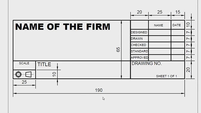
Title Block
The title block is a crucial section of a drawing that contains essential information for identifying the part or assembly represented. It typically includes the drawing number, which is used for reference and organization.
In approved military prints, the title block may also include the name and address of the Government Agency or organization responsible for the drawing, the scale of the drawing, drafting record details, authentication information, and the date.
Revision Block
Located usually in the upper right corner of the drawing, the revision block is used to document any changes made to the drawing. Each change is assigned a unique identification number or letter and is accompanied by a date. In the absence of a revision block, revised drawings may be indicated by adding a letter to the original drawing number.
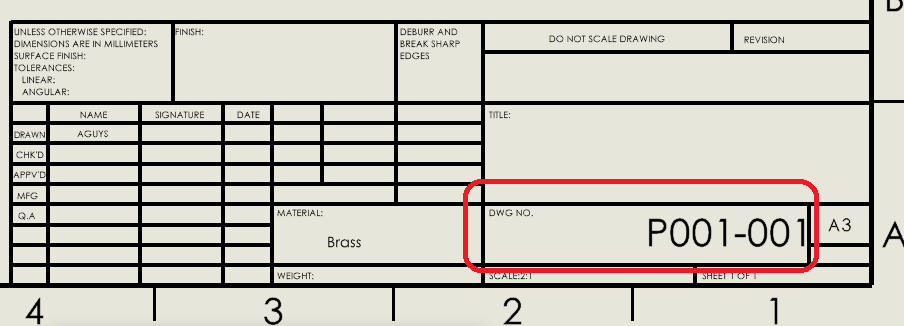
Drawing Number
Every drawing is assigned a unique drawing number, which serves as a distinct identifier. In the case of prints with multiple sheets, where each sheet shares the same number, the drawing number is accompanied by information indicating the sheet number and the total number of sheets in the series.
Reference Numbers and Dash Numbers
Reference numbers appearing in the title block are used to refer to other print numbers, establishing connections between different drawings. Dash numbers are often employed when multiple details are shown on a single drawing.
For instance, if two parts are depicted in one detail drawing, both prints will bear the same drawing number followed by a dash and an individual number, such as 7873102-1 and 7873102-2.
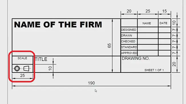
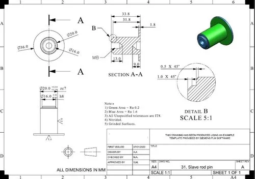
The scale of the drawing is indicated within the title block, providing a ratio that represents the relationship between the size of the drawing and the actual size of the part.
how to read a drawing scale on drawing
It is important to note that measurements should not be taken directly from the drawing itself, as the print may have been reduced in size from the original drawing. Instead, dimensions provided on the drawing should be used for accurate measurements.
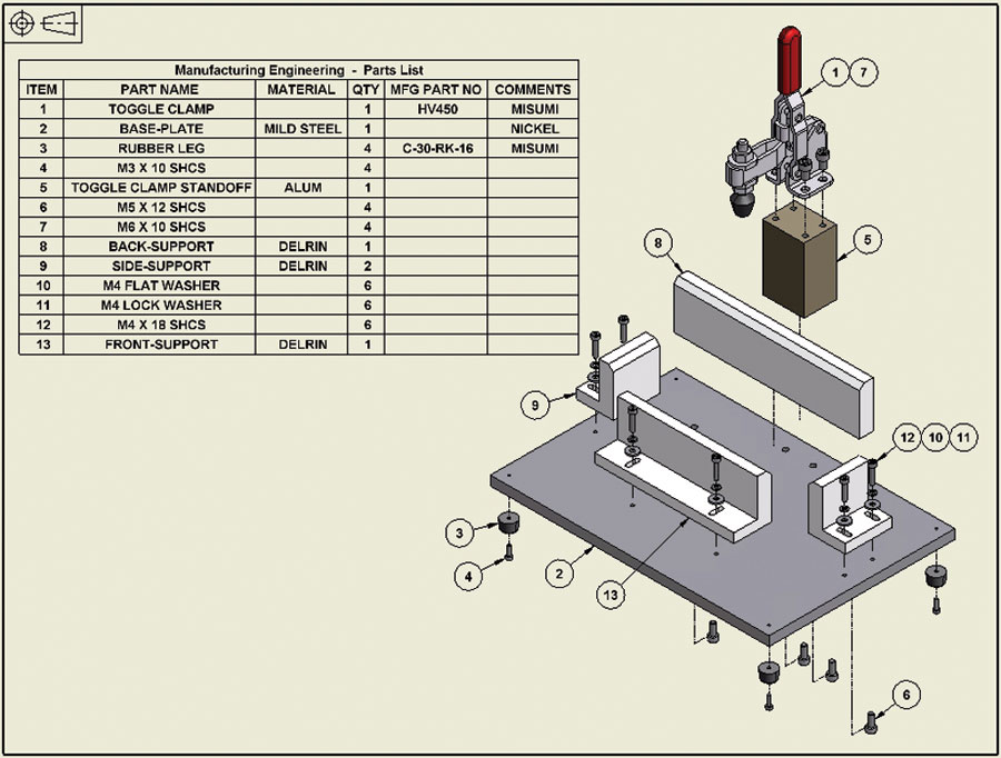
Bill of Material
A dedicated block or box on the drawing, known as the bill of material, contains a list of the necessary stock or materials required to create the assembly represented by the drawing. It specifies the type of stock, size, and the precise amount needed, assisting in the proper identification and procurement of materials for manufacturing.
Image- technet
The Purpose and Elements of Engineering Drawing
Engineering drawings, also known as blueprints or mechanical drawings, provide a comprehensive outline that goes beyond a simple drawing. They contain specific details and information, including dimensions, geometry, tolerances, material type, finish, and hardware.
This wealth of information ensures accuracy and consistency throughout the manufacturing process, enabling the creation of high-quality products.
Information Blocks in Engineering Drawing
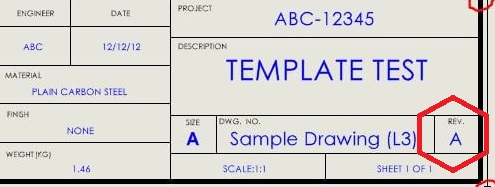
In engineering drawings, information blocks serve as crucial sections that provide important details about the drawing. The title block, typically located in the bottom right-hand corner, offers contextual information such as the company or agency responsible for the drawing, part number and description, material, finish, and revision numbers. It sets the foundation for understanding the drawing’s purpose and specifications.
The revision block, found in the upper right-hand corner, indicates any changes made to the drawing over time. It includes revision descriptions, dates, and approval information, ensuring that the most up-to-date version of the drawing is being referred to.
The bill of materials (BOM) block, often positioned above the title block or in the upper left-hand corner, presents a comprehensive list of the components and quantities required for the project or assembly. It facilitates the proper assembly process and ensures that all necessary parts are accounted for.
Construction Lines in a Drawing
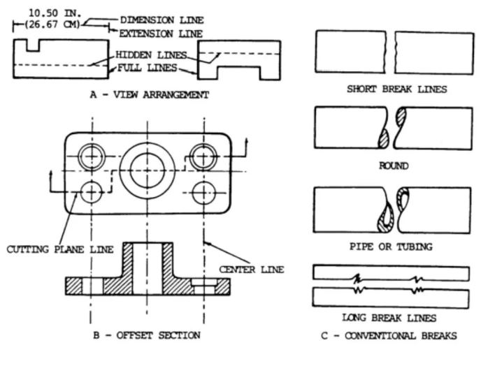
1. Full Lines Full lines are solid lines that represent the visible edges or outlines of an object. They provide a clear representation of the object’s shape and structure. See figure A below.
2. Hidden Lines Hidden lines are composed of short dashes and are used to represent edges that are not visible in the given view of the object. These lines help to illustrate the hidden or obscured features of the object. See figure B below.
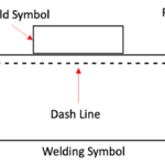
3. Center Lines Center lines consist of alternating short and long dashes. They are used to indicate the exact geometric center of an object or feature. These lines are helpful in establishing symmetry and alignment in the drawing. See figure B below.
4. Cutting Plane Lines Cutting plane lines are dashed lines, usually of the same width as full lines, that extend through the area being cut. They are accompanied by short solid wing lines at each end, forming arrowheads that point in the direction of viewing. Capital letters or numerals are placed beyond the arrowheads to designate the section being cut. See figure B above.
5. Dimension Lines Dimension lines are fine, solid lines that end with arrowheads. They are used to indicate the measured distance between two points on the drawing. Dimension lines provide crucial information about the size and scale of objects or features. See figure A above.
6. Extension Lines Extension lines are fine lines that extend from the outside edges or intermediate points of a drawn object. They indicate the limits or boundaries of dimension lines, helping to establish the specific points being measured. See figure A above
7. Break Lines Break lines are used to indicate a break in the drawing, typically when it is necessary to increase the scale of a drawing while still showing the true size of a uniform cross-section. There are two types of break lines: short break lines and long break lines. Short break lines are usually heavy, wavy, semi-parallel lines that cut off the object outline across a uniform section. See figure C above.
Long break lines, on the other hand, are long dashed parallel lines with each dash connected to the next by a “2” or sharp wave line. These lines help to conserve space on the drawing and emphasize specific sections or details.
Understanding Line Types in Engineering Drawing
Line types in engineering drawings convey crucial information about the object being represented. Visible lines indicate edges that are visible in the relevant view, while hidden lines represent edges that are behind a face.
Phantom lines are used to indicate alternate positions of moving parts or to depict breaks when the conventional type of break is not feasible. Centre lines, consisting of lighter long and short dashes, indicate the exact geometric center of the assembly.
To read and interpret engineering drawings effectively, start by examining the title block for important contextual information. Familiarize yourself with the purpose, part number, material, finish, and other details provided.
Next, visualize the assembly in 3D, using isometric views provided in the drawing as a guide. Refer to the bill of materials to understand the role of each component within the assembly.
Throughout the process, pay attention to dimensions, tolerances, and other specifications indicated in the drawing. Develop an understanding of how different elements interact and contribute to the overall design.
Tips and Best Practices for Reading Engineering Drawing
Mastering the skill of reading engineering drawings takes time and practice. Here are some tips to enhance your proficiency:
Familiarize yourself with industry standards and symbols commonly used in engineering drawings.
Continuously improve your knowledge of geometric dimensioning and tolerancing (GD&T) principles.
Seek clarifications when encountering ambiguous or unclear information in the drawing.
Develop a systematic approach to reading drawings, focusing on one section at a time.
Engage in hands-on application by practicing with a variety of drawings and assemblies.
Conclusion
Reading engineering drawings is a fundamental skill for professionals involved in the manufacturing process. By understanding the purpose, elements, and line types in engineering drawings, you can accurately interpret and implement design specifications. With practice and continuous learning, you can enhance your ability to read engineering drawings effectively, contributing to the production of precise and high-quality products.


: A Comprehensive Guide")


