Understanding Stamped Drawings: Importance, Process, and Alternatives
When it comes to construction projects, obtaining stamped drawings is crucial for obtaining permits and ensuring compliance with required specifications. Stamped drawings bear the seal of a Professional Engineer, indicating that the drawing has been …
When it comes to construction projects, obtaining stamped drawings is crucial for obtaining permits and ensuring compliance with required specifications.
Stamped drawings bear the seal of a Professional Engineer, indicating that the drawing has been reviewed and meets relevant code and safety requirements.
💥In this blog post, we will delve deeper into the purpose of stamped drawings, explore the process involved, and discuss alternative approaches for design validation.💥
What do stamped drawings mean?
Stamped drawings refer to engineering or construction drawings that bear the seal or stamp of a Professional Engineer (PE).
“The stamp indicates that a qualified engineer has reviewed and approved the drawings, certifying that they meet the required codes, regulations, and safety standards. “
✨✨ Stamped drawings provide assurance that the design and specifications of a project or equipment have been reviewed and deemed compliant by a licensed professional. They are often required for obtaining permits and ensuring the quality and safety of construction projects. ✨✨
However, it’s important to note that the stamp does not guarantee the quality of the construction or installation itself. The responsibility for ensuring proper construction lies with the contractors, builders, and other professionals involved in the execution phase of the project.
The Purpose of Stamped Drawings
Stamped drawings serve as evidence that a professionally trained engineer has reviewed the drawing and certified its compliance with codes and safety standards.
The purpose of stamped drawings is to provide assurance and validation that a design meets the required codes, regulations, and safety standards. When drawings are stamped by a Professional Engineer (PE), it signifies that the design has been reviewed and approved by a qualified individual with expertise in the relevant field.
Stamped drawings are important for several reasons:
Compliance: Stamped drawings demonstrate compliance with building codes, zoning regulations, and other applicable standards. They ensure that the design meets the minimum requirements necessary for safety, structural integrity, and functionality.
Permitting: Many jurisdictions require stamped drawings as part of the permitting process. Building officials and regulatory authorities rely on the seal or stamp to verify that the design has been reviewed and approved by a licensed professional.
Liability: Stamped drawings also play a role in liability protection. By having a design reviewed and stamped by a PE, the design professional assumes responsibility for the accuracy and safety of the design within the boundaries of their expertise.
Quality Assurance: Stamped drawings serve as a quality assurance measure, providing confidence that the design has undergone professional scrutiny and meets industry standards. They help to minimize errors, reduce risks, and ensure that the project is executed according to the intended design.
The Stamped Drawings Process
The stamped drawings process involves the review and approval of engineering drawings by a licensed professional engineer (PE) or a qualified authority. The purpose of stamping the drawings is to certify that they comply with applicable codes, regulations, and industry standards, and that they have been prepared by a qualified professional.
Here is an overview of the stamped drawings process:
Preparation of Drawings: The engineer or design professional prepares the engineering drawings according to the project requirements, including architectural, structural, mechanical, electrical, or other relevant disciplines. The drawings should accurately represent the design intent and incorporate all necessary details and specifications.
Review by the Engineer: The engineer thoroughly reviews the drawings to ensure compliance with applicable codes, standards, and project specifications. They verify that the design is structurally sound, safe, and meets all relevant requirements.
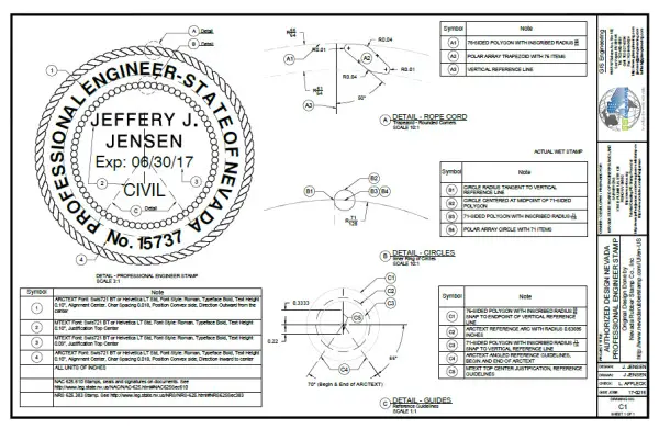
Stamping and Signing: Upon completion of the review, the engineer adds their professional stamp and signature to the drawings. The stamp typically includes the engineer’s name, license number, and professional seal. The stamp signifies that the engineer takes responsibility for the design and certifies its accuracy and compliance.
Submission for Approval: The stamped drawings are then submitted to the appropriate regulatory bodies, clients, contractors, or other stakeholders for review and approval. The reviewing party examines the drawings to ensure compliance with local building codes, zoning regulations, and project specifications.
Approval Process: The reviewing party evaluates the stamped drawings based on various criteria, including structural integrity, safety, compliance with regulations, and adherence to project requirements. They may request revisions or clarifications if any issues or discrepancies are identified.
Revisions and Resubmission: If revisions are required, the engineer or design professional makes the necessary changes to address the comments or concerns raised during the review process. The revised drawings are then resubmitted for further review and approval.
Final Approval and Construction: Once the stamped drawings receive final approval, they serve as the authorized and accepted design documentation for the project. Contractors and construction teams refer to these approved drawings during the construction phase to ensure accurate implementation of the design.
How to get engineering stamped drawings for permitting?
Obtaining stamped drawings can be a challenging process as engineers are held accountable for the accuracy and compliance of the drawings they stamp, adhering to their engineering code of ethics. When a Professional Engineer affixes their signature and seal to drawings, they are legally affirming that the drawings were prepared under their direct supervision.
🟢 One approach to finding a licensed engineer to stamp drawings is to search for semi-retired professional engineers on professional networking platforms like LinkedIn. However, it is essential to verify that their engineering license is still active in the relevant state.
🟢 Another option is to explore platforms such as Craigslist or freelance sites like Upwork to find licensed engineers. It is crucial to ensure that they have errors and omissions liability insurance, as the engineer who stamps the drawings assumes liability for public safety. In the event of any issues or legal matters, the engineer who stamped the drawings may be held accountable.
🟢 Alternatively, seeking the services of an engineering firm specializing in mechanical, electrical, and plumbing (MEP) design can be a viable option. Researching and contacting local MEP firms can help in obtaining a free proposal for the services they offer. These firms have the necessary expertise to prepare and stamp the required drawings for your project, ensuring compliance with regulations and industry standards.
Alternatives to Stamped Drawings
While stamped drawings are commonly used, alternative approaches for design validation exist. We will explore two such alternatives: design reviews and design checking.
Design reviews involve interdisciplinary collaboration and focus on technical aspects, ensuring that all stakeholders provide input and address any necessary changes.
On the other hand, design checking is a quality control process that validates the design and ensures error-free documentation. We will discuss the benefits and considerations of these alternatives.
Examples of Projects Requiring Engineered Stamped Drawings
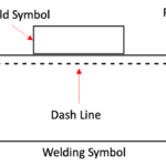
Welding Specifications
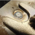
👨🏭 👨🏭 The design mandates that all 2-inch x 4-inch posts must undergo square seam welding, accompanied by 6-inch x 8-inch x ¼-inch baseplates. Any proposed alternatives must be submitted for approval by the customer, contingent upon the review and approval of Engineered Stamped Drawings.
Component Documentation
🌟🌟 Within ten (10) days of the approval of Engineered Stamped Drawings, a comprehensive inventory of components and hardware, including descriptions, part numbers, and quantities, for the Equipment Platform Mezzanine, must be provided.
Foundation Placement
🌟🌟 The Supplier/Contractor is responsible for supplying both Engineered Stamped Drawings and Construction Drawings that outline the precise placement and installation of engineered foundation footings.
Welding Requirements
👨🏭 👨🏭 All 2-inch x 2-inch posts are required to undergo square seam welding, in conjunction with 6-inch x 6-inch x ¼-inch baseplates. Any proposed alternatives must be presented for final approval by the customer after the review and approval of Engineered Stamped Drawings.
✔️✔️ For final design approval by the customer, Engineered Stamped Drawings detailing the equipment platform mezzanine design must be provided. ✔️✔️
Compliance with Standards
✔️✔️ The proposed project should enhance a Public Water System’s (PWS) capacity to meet both current and future national drinking water standards.
Different types of Engineering Drawings
Following the main types of engineering drawings:
Architectural Drawings: These drawings depict the design and layout of a building’s architectural elements, including floor plans, elevations, sections, and details. They provide information on dimensions, materials, finishes, and other architectural features.
Structural Drawings: Structural drawings show the design and construction details of a building’s structural components, such as beams, columns, foundations, and load-bearing walls. They provide information on the size, spacing, and placement of structural elements to ensure the building’s stability and safety.
Mechanical Drawings: Mechanical drawings illustrate the design and installation of mechanical systems within a building, such as HVAC (heating, ventilation, and air conditioning), plumbing, and fire protection systems. They include details on equipment layout, ductwork, piping, and other mechanical components.
Electrical Drawings: Electrical drawings depict the design and installation of electrical systems in a building. They include information on power distribution, lighting fixtures, switches, outlets, and other electrical components. Electrical drawings also show wiring diagrams and circuit layouts.
Civil Engineering Drawings: Civil engineering drawings cover various aspects of infrastructure projects, such as roads, bridges, dams, and utilities. They include site plans, grading and drainage plans, utility layouts, and profiles. Civil engineering drawings provide details on earthworks, stormwater management, utility connections, and other civil engineering elements.
Piping and Instrumentation Diagrams (P&ID): P&IDs are used in process engineering to illustrate the interconnections and control systems of industrial processes. They show piping systems, equipment, instruments, valves, and control loops. P&IDs are crucial for understanding and maintaining process systems in industries like oil and gas, chemical plants, and power generation.
Machine Drawings: Machine drawings provide detailed information on the design and specifications of machines and mechanical equipment. They include assembly drawings, part drawings, and exploded views, showing the arrangement and dimensions of components, tolerances, and manufacturing instructions.
Electronic Circuit Diagrams: These diagrams depict the electrical connections, components, and circuits in electronic systems. They are used in the design and troubleshooting of electronic devices and systems, including printed circuit boards (PCBs), integrated circuits (ICs), and other electronic components.
Geotechnical Drawings: Geotechnical drawings are used in civil engineering and construction projects to depict site conditions, soil profiles, and foundation design. They include information on soil types, bearing capacity, groundwater levels, and other geotechnical parameters relevant to the project.
Survey Drawings: Survey drawings show the measurements, boundaries, and topographic features of a piece of land. They include boundary surveys, topographic surveys, and site plans, providing essential information for land development, construction, and property ownership.
What is a Shop Drawings?
Shop drawings provide a comprehensive representation of the proposed fabrication and assembly of structural elements and the installation details (including form, fit, and attachment) of equipment materials.
Shop drawings include various materials such as diagrams, layouts, schematics, descriptive literature, illustrations, schedules, performance and test data, and similar materials. They serve to explain specific portions of the work required by the contract and can be duplicated, used, and disclosed for any purpose related to the contract.
What is As-Built Drawings?
As-built drawings are submitted by the Contractor or subcontractor at any tier to document the actual construction of a particular structure or work as it has been completed under the contract.
These drawings provide an accurate representation of the completed construction, including any modifications or deviations made during the construction process. The term “as-built drawings” is synonymous with “record drawings.”
What is Record Drawings?
Record drawings refer to a set of construction documents that incorporate clarifications, sketches, and other modifications made by the Architect during the Construction Phase.
They also include significant changes made during construction as shown on the Trade Contractor’s as-built drawings. Record drawings serve as an updated version of the original construction documents, reflecting changes and modifications made during the construction process.
What is Contract Drawings?
Contract drawings include only those drawings specifically titled as such and listed in the specifications or any addendum. These drawings are directly related to the contractual agreement between parties and may be provided by the Commissioner or as supplemental information. They pertain to the specific requirements outlined in the contract.
What is Working Drawings?
Working drawings are the final drawings approved by the relevant authority, such as the Landlord. These drawings serve as the detailed plans for the construction of improvements within a building.
The “Work” refers to all the specified improvements indicated on the working drawings, along with any additional work required by governmental authorities due to the indicated improvements.
Approval of the working drawings does not imply a warranty or guarantee of adequacy or compliance with laws but indicates consent to the drawings. Tenant may be requested to review and approve the working drawings, and the construction work should align substantially with these approved drawings.
What is Construction Drawings?
Construction drawings consist of the final architectural and engineering plans and specifications for the improvements to be constructed by the Tenant within the premises. These drawings provide detailed information required for governmental approvals, building permits, and comprehensive construction documentation for contractors.
They encompass various elements such as partitions, doors, HVAC systems, ceiling systems, lighting fixtures, plumbing installations, electrical installations, telephone installations, fire and life-safety systems, wall finishes, floor coverings, and any other installations specified by the Tenant.
Construction drawings can include modifications or additions to the existing condition of the premises at the time of lease execution.
What is Temporary Clean Coal Technology Demonstration Project?
A temporary clean coal technology demonstration project refers to a time-limited project that demonstrates clean coal technology. It operates for a period of five years or less and ensures compliance with State Implementation Plans (SIP) and other requirements to attain and maintain national ambient air quality standards during and after the project’s termination.
Design Criteria Package
The Design Criteria Package comprises concise, performance-oriented drawings or specifications for public construction projects. Its purpose is to provide sufficient information for Design-Build Firms to prepare bids or responses to the District’s Request for Proposals. The package may also be used for entering into a negotiated Design-Build Contract.
It specifies performance-based criteria for the project, including legal site descriptions, survey information, interior space requirements, material quality standards, schematic layouts, conceptual design criteria, cost or budget estimates, design and construction schedules, site development requirements, utilities, stormwater retention and disposal provisions, and parking requirements.
The Design Criteria Package also requires firms to submit information regarding their qualifications, availability, and past work, including their partners and members.


: A Comprehensive Guide")


