What is a Flange Weld? A flanged corner edge weld refers to a welding technique employed to connect two metal pieces that intersect at a right angle, with one side featuring a flange. This particular …
A flanged corner edge weld refers to a welding technique employed to connect two metal pieces that intersect at a right angle, with one side featuring a flange. This particular joint is frequently utilized in metalworking and fabrication processes to construct various structures, including frames, tanks, and machinery.
To execute an edge weld on a flanged corner, the two metal pieces are aligned at a perpendicular angle, with the flange positioned on one side. The welding process involves creating a weld along the edge where the two metal pieces meet. Typically, a fillet weld is employed for this purpose, which fills the corner of the joint in a triangular shape.
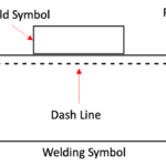
What are Flange Weld Symbols?
Flange weld symbols are specifically used to represent joints that involve the flaring or flanging of edges in light gauge metal structures. These symbols help welders and designers visualize the welding requirements for creating strong and secure connections.
By deciphering flange weld symbols accurately, welders can execute precise welds that meet the specified dimensions and contours.
Understanding Dimensions of Flange Welds
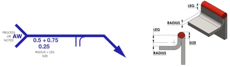
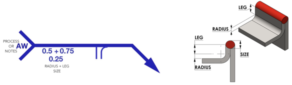
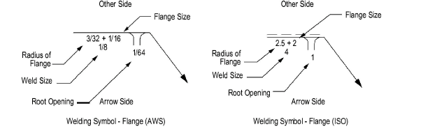
The dimensions of flange welds are represented on the same side of the reference line as the weld symbol. The radius and height above the point of tangency are indicated by showing the radius and height, separated by a plus mark, and placed to the left of the weld symbol.
The important dimensions of a Flanged weld symbol are:
Radius of Flange,
Weld size,
Root opening
Weld direction- arrow side or other side
flanged weld symbol
It is important to note that the radius and height must be read in that order from left to right along the reference line. Additionally, the size (thickness) of the welds is shown by a dimension placed outward of the flange dimensions.
Welding Symbols for Flaring or Flanging Light Gauge Metal Joints
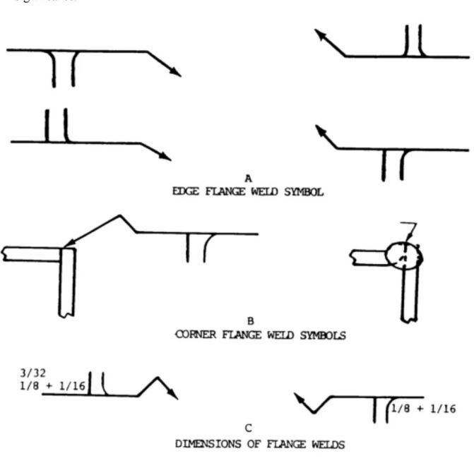
(1) Welding symbols used for light gauge metal joints involving the flaring or flanging of edges to be joined have no arrow or other side significance (Fig. below). These symbols are specifically designed for such joints, and their placement does not indicate a particular side.
(2) Edge flange welds are represented by the edge flange weld symbol (A, Fig. figure below). This symbol is used to depict welds on the edges of flanged metal joints.
(3) Corner flange welds are depicted by the corner flange weld symbol (B, Fig. above). When the corner flange joint is not detailed, a break in the arrow is required to indicate which member is flanged. This break in the arrow helps clarify the specific member involved in the flanging process.
These welding symbols for flaring or flanging light gauge metal joints provide clear instructions on the type and location of the welds required. Proper utilization of these symbols ensures accurate communication and facilitates the correct execution of welding operations.
Dimensions of a Flange Weld
Dimensions of flange welds play a crucial role in accurately representing the size and characteristics of the welds. Here are important considerations regarding the dimensions of flange welds:
(1) Dimensions Placement: The dimensions of flange welds are shown on the same side of the reference line as the weld symbol. This placement ensures that the dimensions are associated with the weld symbol and provide additional information about the weld.
(2) Indicating Radius and Height: To specify the radius and height above the point of tangency, the welding symbol should show the radius and height separated by a plus mark. These values are placed to the left of the weld symbol, along the reference line. The order of reading these values should be from left to right, with the radius indicated first and then the height (C, Fig. above).
(3) Size (Thickness) Representation: The size or thickness of flange welds must be indicated by a dimension placed outward of the flange dimensions. This dimension provides information about the thickness of the weld itself and is positioned outside the flange dimensions (C, Fig. above).
(4) Root Opening Specification: The root opening of flange welds is not typically shown on the welding symbol. If there is a specific requirement for specifying the dimension of the root opening, it must be explicitly shown on the drawing itself. This ensures accurate communication of the desired root opening dimension.
Flash or upset weld symbols, which are used in conjunction with flange weld symbols, have their own significance. These symbols do not possess arrow sides or other side indications. They are centered on the reference line and do not require dimensions to be shown on the welding symbol. The contour symbols for flash or upset welds are indicated in a similar manner as fillet welds.
Flash weld and upset welding symbol
Significance of Flange Weld Symbols
Flange weld symbols serve as a common language between welders, designers, and engineers. They provide precise instructions for creating flange welds, ensuring consistency and adherence to specified dimensions and contours. By accurately interpreting flange weld symbols, welders can achieve structurally sound and visually appealing joints.
Tips for Interpreting Flange Weld Symbols
To effectively interpret flange weld symbols, it is essential to familiarize oneself with the components and variations of these symbols. Understanding the placement and meaning of dimensions, contours, and supplementary symbols is crucial. By studying welding drawings and practicing the interpretation of flange weld symbols, welders can enhance their proficiency and ensure precise execution of welds.
Flange weld symbols are a vital aspect of welding drawings, enabling clear communication and precise execution of welds involving flaring or flanging of edges. By understanding the dimensions, variations, and significance of these symbols, welders can consistently produce high-quality welds that meet the specified requirements.