One of the most common welding symbols is the plug welding symbol, which is used to indicate that a hole in one piece of metal will be filled with a weld. Although the plug welding …
One of the most common welding symbols is the plug welding symbol, which is used to indicate that a hole in one piece of metal will be filled with a weld. Although the plug welding symbol is relatively simple, it can be confusing for those who are not familiar with it.
In this blog article, we will demystify the plug welding symbol, explaining its meaning, how to read it, and the different variations of the symbol that can be used.
By the end of this article, you will have a clear understanding of the plug welding symbol and be better equipped to interpret welding symbols in technical drawings.
What is Plug Welding?
Before we delve into the specifics of the plug weld symbol, it’s crucial to understand plug welding itself. Plug welds are essentially round welds that are made inside an existing hole, most commonly in one piece of metal. The purpose? To weld that piece to another member.
Unlike most other types of welding, plug welding doesn’t require the edges of the metal to be prepared or chamfered. Instead, a hole is drilled or punched into one metal component, and then a weld is applied that adheres to another piece of metal beneath it. This is particularly useful in scenarios where the welder cannot access both sides of the workpiece.
Information to be specified using a Plug Weld Symbol
To properly apply plug welds, certain information must be provided, including:
Hole Size: The dimension specifying the size of the hole where the plug weld will be inserted.
Countersink Angle: The angle of the countersink, which prepares the hole for the plug weld.
Filling Depth: The depth to which the plug weld should be filled within the hole.
Weld Spacing: The specified distance between individual plug welds.
Contour and Surface Finish Reference: If required, any instructions regarding the desired contour or surface finish of the plug weld.
Plug Welding Symbol
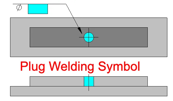
Plug welds are like circular patches made inside a hole that’s already in a piece of metal. This is done to attach that piece to another one. The symbol that tells you to do a plug weld is a square. To the left of this square, you’ll see a symbol that looks like a circle with a line through it – this is the diameter symbol. Right next to this, you’ll find a number that tells you how big the hole for the weld should be.
The plug weld symbol is a simple rectangle. It is used on welding diagrams to indicate where a plug weld is needed and what size it should be. To the left of the symbol, you’ll find the diameter symbol (Ø) along with the number associated with that diameter. This number indicates the size of the hole in which the plug weld will be made.
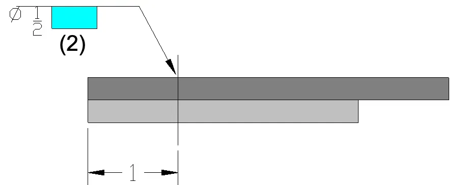
In some blueprints or designs, you might not see the hole marked where a plug weld needs to go. In these cases, measurements are very important to figure out where to do the plug weld. The exact spot will be shown by a line running through the middle of the part.
The information above is telling us that there’s a ½ inch plug weld that’s placed 1 inch away from the edge, measured to the center of the weld.
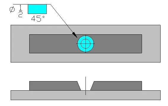
Sometimes, the hole for the plug weld might have a slant or ‘countersink‘. This is known as the included angle of countersink. This angle is shown under the square symbol for the weld, or above it if the weld is to be made on the opposite side. When you’re working out the size of the hole, keep in mind that the diameter refers to the smallest part of the hole, which is at the bottom of the weld.
f there’s no countersink included, you’ll need to follow the rules and methods of your workshop to decide if an angle is needed. Most workshops have set ways of doing things that are done regularly. If an angle is needed, it might be mentioned in the welding instructions for the plug welds you’re doing.
If you need to do more than one plug weld, there will be an extra part added to the symbol. This will be a number in brackets, like (2) for instance.
When you’re doing a plug weld, it’s important to know how deep you need to fill the hole. If you need to fill the whole hole, then the square symbol for the weld will be empty. This means there’s no number inside the square. If you only need to fill the hole part of the way, then this will be shown inside the square. This number will be a fraction and tells you how many inches to fill the hole, not necessarily what portion of the hole to fill.
Another detail that might be added to this weld symbol is the pitch, or the space between multiple welds. This is shown to the right of the square symbol, and it’s a number that tells you the space from the center of one weld to the center of the next weld.
Plug Weld with Supplementary Contour Weld Symbol
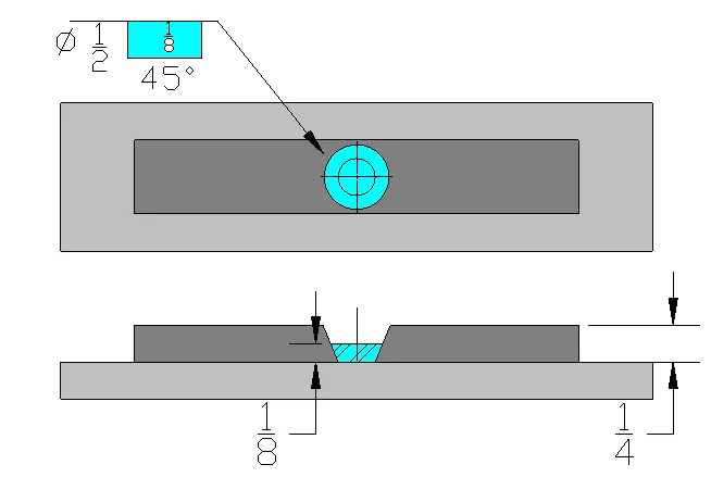
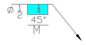
Plug welds might have a contour symbol, which will be placed under the square symbol or the countersink angle if it’s on the arrow side, or above if it’s on the other side of the reference line. There are many different types of contours and finishes, and these are shown in extra welding symbols. This symbol is telling us:
This is a plug weld.
It’s on the arrow side.
The hole for the weld is ½ inch across.
The hole needs to be filled by 1/8 inch.
The countersink angle is 45 degrees.The contour is flat.
The size of a plug weld is typically indicated by the diameter of the hole and is positioned on the left side of the weld symbol, as depicted in Figure above. It’s important to note that the governing design specification may establish a relationship between the minimum hole diameter and the material thickness in which the plug weld is to be made.
For instance, CSA W59 and AWS D1.1 specify the minimum hole diameter as:
dmin = t + 8mm (CSA W59 [metric])
= t + 5/16 in. (CSA W59 and D1.1 [imperial])
Angle of Countersink
To facilitate welding and provide easier access to the root, countersunk holes with sloping sides may be utilized. If specified in the welding symbol, the angle of countersink should be placed outside the horizontal side of the weld symbol.
Depth of Filling
If complete depth of filling is required for the plug weld, it does not need to be explicitly specified in the welding symbol. However, if a depth of filling less than complete is necessary, it must be specified and shown within the weld symbol.
In summary, the size of plug welds is determined by the hole diameter, with the minimum diameter often related to the material thickness. The angle of countersink, if applicable, is positioned outside the horizontal side of the weld symbol.
The depth of filling, if less than complete, must be specified within the weld symbol. These specifications ensure proper execution of plug welds and adherence to welding requirements.
Spacing of Plug Welds
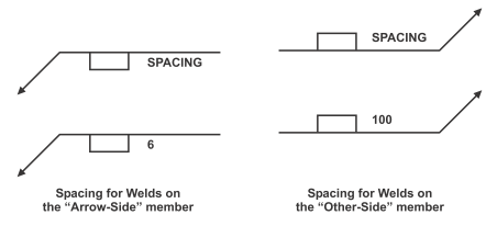
The spacing of plug welds is determined by the concept of pitch, which represents the center-to-center distance between individual plug welds. Similar to other types of welds, the standard convention is to indicate the length dimension on the right side of the weld symbol, as illustrated in Figure below.
Spacing of Plug Welds
By specifying the pitch, the drawing communicates the desired spacing between plug welds, ensuring consistency and proper alignment during the welding process. This information helps welders accurately position and distribute the plug welds according to the specified requirements.
Interpreting the Plug Weld Symbol
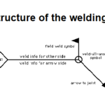
The placement of the plug weld symbol on the reference line is also important. If the symbol is placed above the line, the weld is to be made on the arrow side. If it is placed below the line, the weld should be made on the side opposite the arrow.
Additional information may be included with the symbol. For instance, the number of plug welds required in a particular joint might be indicated. Or, specific instructions about the welding process might be provided in the tail of the symbol.
The Importance of the Plug Weld Symbol
Understanding the plug weld symbol is vital for anyone involved in the welding industry. It ensures that welders, engineers, and designers are all on the same page, minimizing confusion and errors.
Moreover, it provides a standardized way to convey complex information quickly and clearly. This not only enhances efficiency but also contributes to the overall quality and safety of the welding project.
The symbols for plug welds and slot welds are not to be used to represent fillet welds within holes.
Arrow and Other Side Indication of Plug and Slot Welds
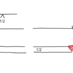
When indicating plug or slot welds, holes or slots on the side of the joint where the arrow is pointing will have the weld symbol placed on the side of the reference line facing the viewer. For holes or slots on the other side of the joint, the weld symbol will be placed on the side of the reference line away from the viewer.
Plug Weld Dimensions
The dimensions of plug welds will be displayed on the same side of the reference line as the weld symbol. The size of the weld will be shown to the left of the symbol. The included angle of countersink for plug welds will follow the user’s standard, unless specified otherwise. If the included angle of countersink is not the user’s standard, it will be indicated above or below the weld symbol.
Depth of Filling of Plug and Slot Welds
Unless otherwise specified, plug and slot welds should be fully filled. If the depth of filling is less than complete, the depth will be indicated in inches inside the weld symbol.
Details of Slot Welds
Specific details such as length, width, spacing, included angle of countersink, orientation, and location of slot welds cannot be shown on the welding symbols. These details will be provided on the drawing or through a separate detail referenced on the welding symbol, following the usual location conventions.
Surface Contour of Plug and Slot Welds
The surface contour of plug and slot welds will be indicated in the same way as fillet welds.
Wrapping Up
The plug weld symbol, though seemingly simple, is a powerful tool in the hands of those in the welding industry. It serves as a testament to the importance of clear communication in complex processes. Whether you’re a seasoned welding professional or a student just starting in the field, understanding the plug weld symbol is a crucial step in mastering the art and science of welding.
Dr. Kumar is a PhD-qualified Welding and Materials Expert with a career spanning 18+ years across metallurgy and NDT. A triple-threat in the industry, he is an IWE, AWS-CWI, and ASNT NDT Level III certified professional. Dr. Kumar is the author of several leading technical resources and is a premier specialist in welding symbol instruction, dedicated to improving global standards in welding engineering and inspection.
Dr. Kumar is a PhD-qualified Welding and Materials Expert with a career spanning 18+ years across metallurgy and NDT. A triple-threat in the industry, he is an IWE, AWS-CWI, and ASNT NDT Level III certified professional. Dr. Kumar is the author of several leading technical resources and is a premier specialist in welding symbol instruction, dedicated to improving global standards in welding engineering and inspection.