What is Kerf in Welding? Kerf in welding refers to the width of material that is removed during a cutting operation, specifically in relation to the width of the weld bead. The size of the …
Kerf in welding refers to the width of material that is removed during a cutting operation, specifically in relation to the width of the weld bead. The size of the kerf is influenced by the welding process and power source utilized.
Once a specific point along the cutting line reaches a bright cherry red color, proceed to fully open the cutting oxygen valve.
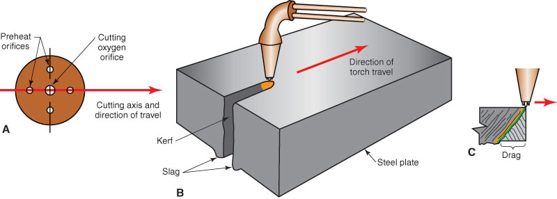
The emission of oxygen through the center of the tip, known as the oxygen jet, induces the heated metal to oxidize and burn away, ultimately forming the cut known as the kerf.
“Kerf = Width“
A reliable indicator of a successful cutting operation is the presence of the slag stream at the bottom of the cut. For steel plates with a thickness under 1″ (25.4mm), an optimal slag stream should pass directly through the plate.
When cutting steel plates thicker than 1″ (25.4mm), a slight drag is desirable to ensure the appropriate consumption of oxygen, resulting in a consistent cut.
“Kerf refers to the width of a cut or the width of material that is eliminated through a cutting procedure.“
What is Drag?
Drag refers to a measurement, taken in the direction of travel, between the entry and exit points of the cutting jet, as depicted in Figure above. If the slag stream significantly lags behind the torch tip’s movement, possible causes could include incorrect flame adjustment, inadequate cutting oxygen pressure, or excessively fast tip travel without sufficient preheating of the metal.
In addition to denoting the width of the weld bead, kerf can also refer to the waste material produced during metal cutting, commonly known as slag. Controlling the width of the weld bead is crucial for welders as it directly impacts joint strength and minimizes waste material.
Typical Kerf Width for 1/2” thick C.S.:
Plasma: 0.150”
Oxy-Fuel: 0.045”
Waterjet: 0.035”
Laser: 0.025”
Techniques to Control Kerf
Welders employ various techniques to regulate the width of the weld bead, including:
Adjusting Oxygen Flow
To control the width of the kerf during gas cutting, one important technique is adjusting the flow rate of oxygen. By increasing or decreasing the oxygen flow, welders can regulate the intensity of the cutting jet and determine the amount of material being removed. This adjustment directly affects the width of the kerf, allowing for precise control over the cutting process.
Optimizing Torch Angle
The angle at which the torch is held during gas cutting plays a significant role in kerf control. By optimizing the torch angle, welders can achieve better heat distribution and penetration, which directly influence the width of the kerf. Experimenting with different torch angles helps find the optimal position for controlling the desired kerf width.
The speed at which the torch is moved along the cutting line has a direct impact on the width of the kerf. Slower cutting speeds tend to widen the kerf, while faster speeds can result in a narrower cut. Finding the right balance and controlling the cutting speed is essential for achieving the desired kerf width in gas cutting operations.
Utilizing Cutting Tips with Varying Sizes
Gas cutting torches offer a range of cutting tips with different orifice sizes. Selecting cutting tips with larger orifices can widen the kerf, while smaller orifices produce narrower cuts. By choosing the appropriate cutting tip size for the specific application, welders can effectively control the width of the kerf during gas cutting.
Monitoring Preheating
Preheating the material before gas cutting can significantly impact the width of the kerf. Proper preheating helps reduce the heat input required during cutting, resulting in a narrower kerf. It is important to carefully monitor and control the preheating process to achieve the desired kerf width while ensuring the material is adequately prepared for cutting.
The distance between the torch and the workpiece, known as the torch-to-work distance, plays a crucial role in controlling the kerf width. Maintaining a consistent and appropriate torch-to-work distance ensures uniform heat distribution and helps control the width of the kerf during gas cutting. Proper torch positioning is essential for achieving precise and accurate cuts.


")


