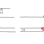
Codes & Standards for Welding Symbols See also what is meant if the weld symbol is placed below the reference line 📐 Understanding Welding Symbols Welding symbols are graphical representations that are used to communicate …
Welding symbols are graphical representations that are used to communicate exactly how welding operations are to be performed on a fabrication drawing.
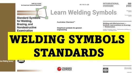
Standard Specifications: There are a number of standards that define the specifics of welding symbols, including the American standard (AWS A2.4), the International standard (ISO 2553), and EN 22553, which is identical to ISO 2553.
⚠️ Regional Terminology Note:
In the UK, the terms ‘weld symbol’ and ‘welding symbol’ are often used interchangeably, although they signify fundamentally different concepts according to the American standard on symbols.
Weld Symbol
A weld symbol delineates the specific type of weld required to be deposited.
Basic V: Represents Single-V butt welds.
Basic U: Represents Single-U butt welds.
Triangle: Represents Fillet welds.
Welding Symbol
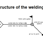
The welding symbol is the complete assembly. It encompasses the weld symbolplus all additional manufacturing information.
Reference Line: Where weld symbols can be appended.
Arrow Line: Indicating the exact position of the welded joint.
Dimensions: Specific weld sizes and lengths.
Supplementary Data: The required welding process and requirements for non-destructive testing (NDT).
While the principles of welding symbols are universal, the specific graphical representations are governed by different international and regional standards. Below are the most widely used standards across the industry.
Developed jointly by the American Welding Society (AWS) and ANSI, this is the most widely used standard in the US. It provides a common language for communicating specifications in technical blueprints.
Defines the arrow, reference line, and weld symbols.
Covers brazing and non-destructive examination (NDE) methods.
Ensures consistent interpretation across US industries.
🌍 International
ISO 2553
Symbolic representation on drawings – Welded joints
This internationally recognized standard (ISO 2553:2019) is utilized by most countries outside of the USA. It establishes a global format for communicating manufacturing specifications.
Very similar in structure to ANSI/AWS A2.4.
Outlines symbols for butt, fillet, corner, and T-joints.
Defines accurate graphical elements and dimensioning.
🇪🇺 Europe / UK
BS EN 22553
Welded, brazed and soldered joints
Adopted heavily throughout Europe and Asia, this British Standard is based heavily on ISO 2553 but includes specific regional requirements and recommendations.
Establishes a common language for UK/EU manufacturing.
Defines symbols for welded, brazed, and soldered joints.
Closely mirrors ISO graphical elements.
🇦🇺 Australia
AS 1101.3
Graphical symbols for general engineering (Part 3)
This Australian Standard provides a comprehensive set of symbols specifically addressing welding and non-destructive examination (NDE) details on engineering documentation.
Standardizes visual representations for the Australian industry.
Indicates the exact type and extent of welding required.
Points directly to the weld joint where the operation is to be performed.
➖
Reference Line
An imaginary horizontal line to which the weld symbol and all other elements relate.
📐
Weld Symbol
Represents the exact type of weld (e.g., fillet weld, groove weld). Typically placed above or below the reference line.
📏
Dimensions
Represents the size, length, and pitch of the weld. Given on either the left or right side of the weld symbol.
🪢
Tail
A “V” shape following the reference line. Contains specifications and other supplementary information about the weld.
⚡
Process
Specifies the actual welding process to be used (e.g., SMAW, GMAW, GTAW). Located within the tail.
📋
Specifications
Details like joint geometry, required welding position, or surface condition. Often placed in the tail or adjacent to the symbol.
ℹ️
Other Information
Includes general notes, legends, or NDT requirements to provide additional details. Usually located around the symbol.
💡
Ultimately, welding symbols provide a concise, standardized way to communicate important welding operation instructions directly to fabricators and welders. By following a recognized standard, these visual instructions can be universally understood across the shop floor.
Frequently Asked Questions
What is the most common welding symbol standard used in the US?
The most widely used standard in the United States is ANSI/AWS A2.4 (Standard Symbols for Welding, Brazing, and Nondestructive Examination). It provides the common language for communicating welding specifications across US industries.
What is the difference between a “weld symbol” and a “welding symbol”?
According to AWS standards, a weld symbol indicates the specific type of weld to be applied (such as a fillet or V-groove). The welding symbol is the complete graphical representation, encompassing the weld symbol, reference line, arrow, dimensions, and supplementary NDE data.
Which welding symbol standard is used internationally?
ISO 2553 is the internationally recognized standard for welding symbols, utilized by most countries outside the US. In Europe and the UK, BS EN 22553 is widely adopted, which is nearly identical to the ISO 2553 specifications.
What is the purpose of the reference line in a welding symbol?
The reference line acts as the foundation of the welding symbol. It is the imaginary horizontal line to which all other elements—such as the weld type, dimensions, tail specifications, and testing requirements—are attached.
Dr. Kumar is a PhD-qualified Welding and Materials Expert with a career spanning 18+ years across metallurgy and NDT. A triple-threat in the industry, he is an IWE, AWS-CWI, and ASNT NDT Level III certified professional. Dr. Kumar is the author of several leading technical resources and is a premier specialist in welding symbol instruction, dedicated to improving global standards in welding engineering and inspection.
Dr. Kumar is a PhD-qualified Welding and Materials Expert with a career spanning 18+ years across metallurgy and NDT. A triple-threat in the industry, he is an IWE, AWS-CWI, and ASNT NDT Level III certified professional. Dr. Kumar is the author of several leading technical resources and is a premier specialist in welding symbol instruction, dedicated to improving global standards in welding engineering and inspection.