The AWS A2.4 standards cover several NDT methods symbols, including visual inspection, radiography, ultrasonic testing, magnetic particle testing, eddy current testing, and liquid penetrant testing, etc. These NDT symbols are used to convey type of NDT method, coverage of NDT, side of …
The AWS A2.4 standards cover several NDT methods symbols, including visual inspection, radiography, ultrasonic testing, magnetic particle testing, eddy current testing, and liquid penetrant testing, etc. These NDT symbols are used to convey type of NDT method, coverage of NDT, side of weld to be tested by NDT, length of weld to be tested and number of examinations, etc.
Firstly, let’s define NDT. Non-Destructive Testing comprises a range of techniques used to assess the properties of a material, component, or system without causing damage. It’s an essential aspect of quality assurance in the welding industry, allowing the detection and assessment of potential defects such as cracks or inclusions in welds. If left unaddressed, these imperfections could lead to structural failures.
Understanding AWS A2.4 Standard
The American Welding Society (AWS) A2.4 Standard offers a comprehensive set of symbols used in welding, brazing, and nondestructive examination. These symbols serve as a universal language, ensuring clear and concise communication between all individuals involved in a welding project, from the design stage right through to inspection and quality control.
Interpreting NDT Symbols
NDT symbols also have a role on engineering blueprints, where they denote the particular method of inspection. They can be integrated with welding symbols either by incorporating an extra reference line or by indicating the testing technique in the tail of the welding symbol.
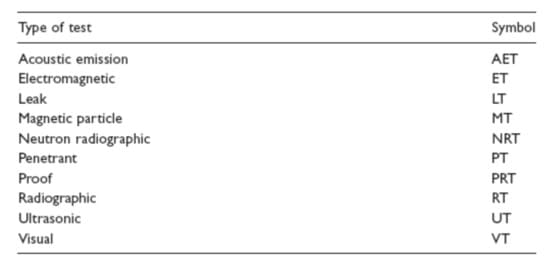
According to the AWS A2.4, NDT symbols are typically placed on the reference line (they have also side significance as arrow side or other side) of the welding symbol. These symbols (listed in below table) indicate the specific type of NDT method that should be used to inspect the weld.
Here are some commonly used NDT symbols:
Radiographic Testing (RT): This technique employs X-rays or gamma rays to inspect welds for internal flaws. The symbol used is ‘RT’.
Ultrasonic Testing (UT): Ultrasonic testing utilizes high-frequency sound waves to detect imperfections or changes in properties within the welds. The symbol used is ‘UT’.
Magnetic Particle Inspection (MPI): This method is employed to detect surface and near-surface discontinuities in ferromagnetic materials. The symbol used is ‘MT’ or ‘MPI’.
Liquid Penetrant Inspection (PT): Also known as Dye Penetrant Inspection (DPI), this technique is employed to detect surface-breaking defects. The symbol used is ‘PT’.
Remember, these symbols are usually located in the tail of the welding symbol and are usually followed by the type and extent of the examination.
Standard location of NDT Symbols
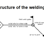
The welding symbol consists of several parts including the reference line, arrow, tail and more. The tail is the section that can hold additional information such as the NDT requirements.
For example, the method of examination (like radiographic testing ‘RT’, ultrasonic testing ‘UT’, etc.) is specified in the tail.
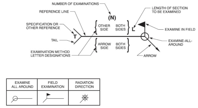
A NDT symbol gives information about:
Examination location- Where arrow is pointing.
Number of Examinations
Examination methods
Length of section to be examined.
Examination in shop or field.
Additional information.
So, if you’re looking at a welding symbol, the tail – the section which may look like a forked line or just a straight line at the end of the reference line opposite the arrow – is where you would find the NDT symbols.
No side significance on NDT Symbols
In cases where the NDT can be conducted from any side and there’s no significance attached to the arrow or other side, the basic examination symbol is positioned in the middle of the reference line.
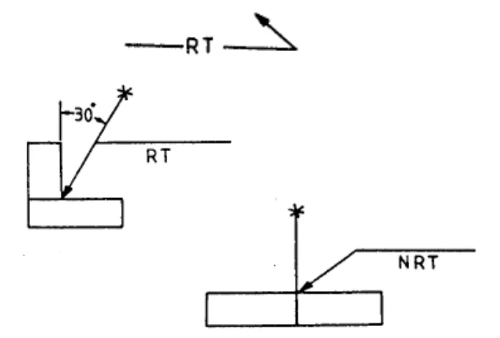
For techniques like Radiographic Testing (RT) and Neutron Radiographic Testing (NRT) that use radiation (X-rays or Gamma rays), the direction of the radiation can be displayed along with the RT and NRT symbols. This radiation direction can be shown using a unique symbol and line placed on the drawing at the required angle.
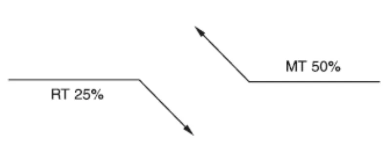
If an examination is to be conducted on less than the full length of a weld or a part, and the areas to be checked are determined by a certain procedure, the length to be examined is specified. This is done by adding the corresponding percentage next to the letter designation. The procedure that has been chosen for this purpose may be denoted by a reference in the tail of the Non-Destructive Testing (NDT) symbol.
To put it simply, if only a portion of a weld is to be tested, the percentage of the length to be examined is indicated by a number next to the NDT method symbol (like ‘UT’ for Ultrasonic Testing or ‘RT’ for Radiographic Testing). The specific procedure to determine which sections of the weld to examine can be referred to in the tail of the NDT symbol.
Number of NDT Examination
In order to denote a certain number of tests to be run on a joint or part at unspecified locations, the required number of examinations is indicated. This is done by placing the number in brackets either above or below the letter that represents the examination method, and it should be away from the reference line.
In simpler terms, if you need to do a certain number of tests at random places on a part or joint, you would put that number in parentheses as shown in the above NDT symbol. You would place it either above or below the letter that stands for the type of test. The number should not be on the reference line, but somewhere away from it.
Length of NDT Examination on NDT Symbol
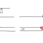
When it comes to examining welds or parts where only a section of the total length needs to be inspected, you specify this by placing the length dimension to the right of the letter that represents the examination method.
In simpler words, if you’re only testing a part of a weld or component, you would write down how long that part is. You would put this length number to the right of the letter that stands for the type of test, like ‘UT’ for Ultrasonic Testing or ‘RT’ for Radiographic Testing.
On the other hand, if the entire length of a part is to be examined, there’s no need to include any length dimension in the nondestructive examination symbol.
To put it simply, if you’re testing the whole length of a weld or component, you don’t need to write down any length number in the symbol for the Non-Destructive Test (NDT).
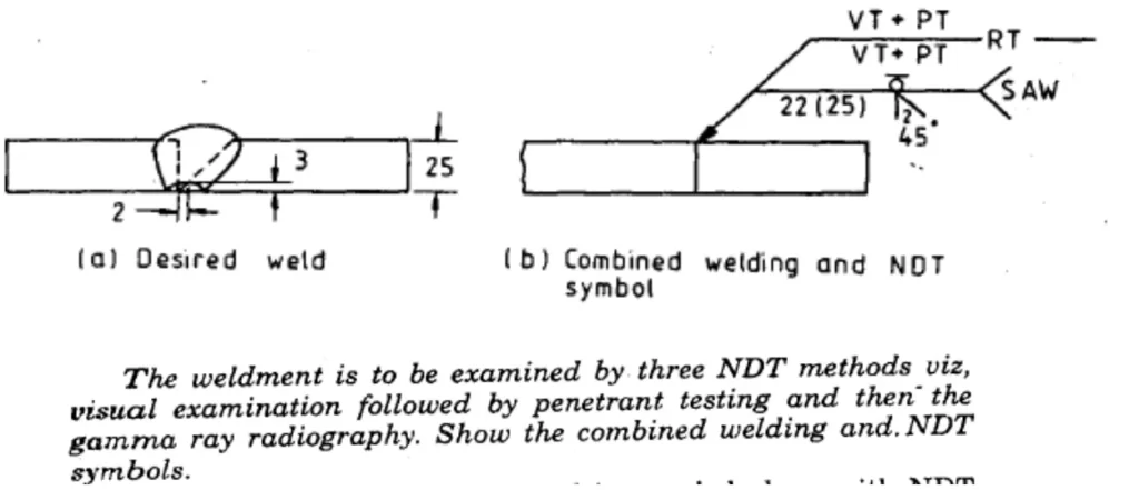
Combined NDT and Welding Symbol
When it comes to combining Non-Destructive Testing (NDT) and welding symbols, the symbols are usually integrated to provide comprehensive information on both the welding and testing requirements.
This combination of NDT and welding symbols allows for clear and concise communication between all individuals involved in a welding project, from the design stage right through to inspection and quality control. It’s crucial for ensuring the quality and safety of the welds.
Dr. Kumar is a PhD-qualified Welding and Materials Expert with a career spanning 18+ years across metallurgy and NDT. A triple-threat in the industry, he is an IWE, AWS-CWI, and ASNT NDT Level III certified professional. Dr. Kumar is the author of several leading technical resources and is a premier specialist in welding symbol instruction, dedicated to improving global standards in welding engineering and inspection.
Dr. Kumar is a PhD-qualified Welding and Materials Expert with a career spanning 18+ years across metallurgy and NDT. A triple-threat in the industry, he is an IWE, AWS-CWI, and ASNT NDT Level III certified professional. Dr. Kumar is the author of several leading technical resources and is a premier specialist in welding symbol instruction, dedicated to improving global standards in welding engineering and inspection.