In manufacturing, quality control is of utmost importance to ensure that products meet the desired specifications and standards. One crucial aspect of quality control is inspection, which involves assessing the dimensions, characteristics, and overall quality …
One crucial aspect of quality control is inspection, which involves assessing the dimensions, characteristics, and overall quality of manufactured parts.
“Inspection symbols on engineering drawings serve as a way to indicate the desired method of examination.”
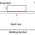
Nondestructive examination symbols (NDE) are included in conjunction with welding symbols either by adding an extra reference line or by specifying the examination method within the tail of the welding symbol.
To effectively communicate inspection requirements and results, inspection symbols play a vital role.
In this blog post, we will explore the significance of inspection symbols and how they contribute to maintaining high-quality standards in manufacturing processes.
Elements of Inspection Symbols
Nondestructive examination symbols consist of several essential elements, including:
Reference line: A line used as a base for positioning other symbols and indicating the area to be examined.
Arrow: An arrowhead attached to the reference line, pointing towards the location of the examination.
Tail: A line connected to the arrowhead or reference line, used for incorporating examination method letter designations.
Examination method letter designations: Letters or abbreviations representing specific nondestructive examination methods, such as “RT” for radiographic testing, “UT” for ultrasonic testing, or “PT” for liquid penetrant testing.
Extent of examinations: Indications specifying the scope or extent of the examination, such as “SP” for spot examination or “100%” for a full examination.
Specifications, codes, and other references: Additional information or references that provide detailed instructions, standards, or codes related to the examination process.
Supplementary symbols: Additional symbols used to convey specific instructions or requirements related to the nondestructive examination, such as symbolizing the use of a particular technique or equipment.
These elements work together to create a comprehensive nondestructive examination symbol, providing clear and concise information about the examination method, scope, and any supplementary instructions or references needed for accurate and effective inspection.
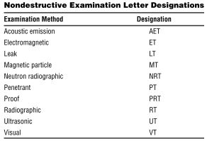
NDT Examination Methods Letter Designations
Nondestructive Testing (NDT) examination methods are commonly represented by letter designations. These designations serve as shorthand representations for different NDT techniques.
Here are some commonly used NDT examination method letter designations:
RT – Radiographic Testing: This method uses X-rays or gamma rays to examine the internal structure of a component or material for defects or discontinuities.
UT – Ultrasonic Testing: Ultrasonic waves are used to detect internal flaws, measure thickness, and assess material properties by analyzing the reflection and transmission of sound waves.
PT – Liquid Penetrant Testing: A liquid dye is applied to the surface of a component, and after a specified time, excess dye is removed. The remaining dye is then visually inspected for indications of surface defects.
MT – Magnetic Particle Testing: This method uses magnetic fields and iron particles to detect surface and near-surface defects in ferromagnetic materials.
ET – Eddy Current Testing: Eddy currents induced in conductive materials are used to detect surface and near-surface defects, measure conductivity, and sort materials based on their electrical properties.
VT – Visual Testing: This method involves direct visual inspection of the surface or structure to identify visible defects, such as cracks, corrosion, or surface irregularities.
AE – Acoustic Emission Testing: This technique detects and analyzes the transient elastic waves generated by the release of energy from a localized source within a structure or component.
LT – Leak Testing: This method is used to detect and locate leaks or the presence of fluid or gas in a sealed component or system.
IR – Infrared Thermography: Infrared cameras are used to detect variations in thermal patterns and identify anomalies that may indicate defects or malfunctions.
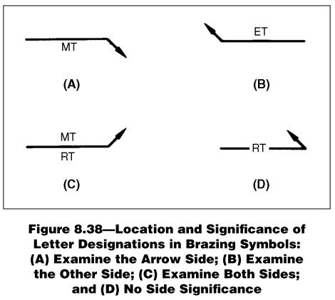
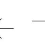
In Figure below, the positions of the letter designations representing NDT examination methods are illustrated, along with their corresponding significance.
The location of these symbols in relation to the reference line indicates whether the examinations are to be performed on the arrow side or the other side of a joint.
To indicate that examinations are to be performed on the arrow side of a joint, the examination method letter designation symbol is placed below the reference line. Figure (A) demonstrates this convention, with the symbol positioned below the reference line.
Other Side Examinations
Examinations to be performed on the other side of the joint are indicated by placing the basic examination symbol above the reference line. Figure (B) above illustrates this arrangement, with the symbol positioned above the reference line.
Both Sides Examinations
When examinations are required on both sides of the joint, the basic examination symbols are positioned on both sides of the reference line. This is shown in Figure (C), where the symbols are placed on both sides of the reference line.
No Arrow-Side or Other-Side Significance
In cases where the examination can be performed from either side or when there is no specific arrow-side or other-side significance, the basic examination symbols are centered within the reference line. Figure (D) presents this arrangement, with the symbols centered in the reference line.
These positioning conventions help clearly indicate the intended location of the NDT examinations and ensure accurate interpretation and execution of the inspection process.
Scope of NDT Inspection or Examination via NDT Inspection Symbol
This method of inspection symbol is applied to provide information about the scope of NDT Examination such as length to be inspected, number of examination, area to be inspected and supplementary information.
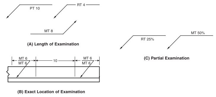
Length to be Inspected or Examined
To indicate that the examination pertains specifically to the length of a section, the desired length is positioned to the right of the NDE symbol. Figure (A) below provides an illustration of this convention.
In situations where both the exact location and length of the section to be examined need to be shown, appropriate dimensions are included in the drawing, as demonstrated in Figure (B).
If no length dimension is included in the nondestructive examination symbol, it is understood that the entire length of the workpiece is to be examined.
However, when a partial examination of the length of a weld or workpiece is specified, and the examination locations are determined by a specified procedure, the length to be examined is indicated by placing the corresponding percentage to the right of the letter designation. Figure (C) provides an example of this notation.
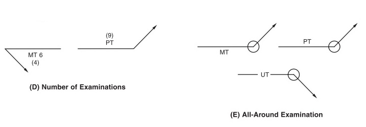
Number of Examination
Conventional methods are also employed to indicate the number of examinations required. When multiple examinations need to be conducted on a joint or part at random locations, the number of examinations is denoted within parentheses, either positioned above or below the letter designation.
This is exemplified in Figure (D). If no specific number is specified, it implies that only one examination needs to be performed.
Figure (E) demonstrates the utilization of the examine-all-around symbol. This symbol is employed to signify that a comprehensive examination is necessary for a continuous joint, such as a circumferential pipe joint.
NDT Inspection Symbols for area to be Inspected
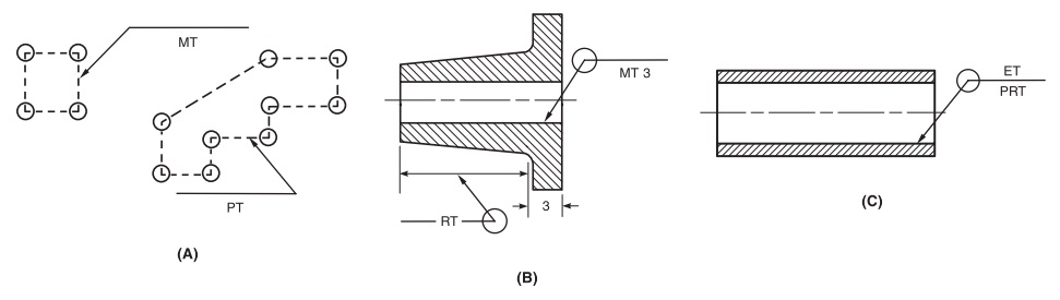
Various conventions are employed to prescribe the nondestructive examination of specific areas on a workpiece, and these conventions are illustrated in Figure below. Here are the explanations for each convention:
Plane Area Examination:
To specify the examination of a plane area, the target area is outlined on the drawing using straight broken lines, with a circle placed at each change of direction.
The appropriate letter designation representing the nondestructive examination method is then included within the enclosed area.
This is demonstrated in Figure (A). The area can be located using coordinate dimensions, which would be indicated on the drawing.
Examination of Areas of Revolution
When the nondestructive examination of areas of revolution is required, the area to be examined is indicated using the examine-all-around symbol along with the relevant dimensions.
For example, in Figure (B), the upper symbol signifies that the bore of the hub should be inspected using magnetic particle examination, covering a distance of 3 inches from the flange face.
The lower symbol indicates that an area of revolution should be examined radiographically, with the width of the area specified using the dimension line.
Pipe or Tube Examination
The symbol used in Figure (C) denotes that a pipe or tube should undergo an internal proof examination and an external electromagnetic examination.
As no specific dimensions are provided, it is understood that the entire length of the pipe or tube is to be inspected.
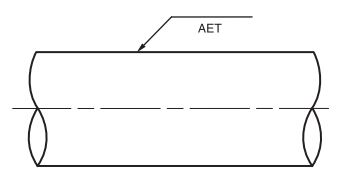
Acoustic Emission Examination
Acoustic emission examination is typically performed on an entire component or a large portion of it, such as a pressure vessel or a pipe.
Therefore, the symbol shown in Figure below is used to indicate the application of this examination method, without specific reference to the location of the sensors.
These conventions help specify the areas of interest for nondestructive examination and the corresponding methods to be applied, ensuring clear communication and accurate inspection procedures.
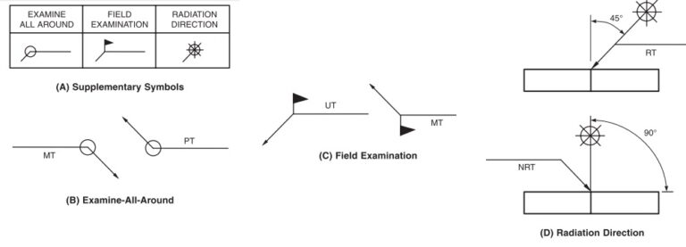
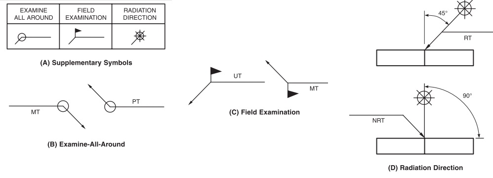
Supplementary symbols are utilized in conjunction with nondestructive examination symbols to provide additional information.
Three types of supplementary symbols are commonly employed, as depicted in Figure below.
Here’s an explanation of each symbol:
Examine-All-Around Symbol: The examine-all-around symbol indicates that the examination is to be conducted around the entire weld, joint, or weldment. Examples of its usage are presented in (B).
Field Examination Symbol: The field examination symbol signifies that the examination needs to be performed in the field, as opposed to a shop or the place of initial construction. Examples of this symbol are shown in Figure (C).
Radiation Direction Symbol: The radiation direction symbol is used in conjunction with radiographic (RT) and neutron radiographic (NRT) examination symbols. It indicates the direction of radiation to be employed in radiographic testing. The symbol consists of a star-like shape representing the radiation source and a line positioned in the drawing at the desired angle. The angle is specified in degrees.