ISO Weld Symbols ISO (International Organization for Standardization) provides standardization guidelines for various aspects of welding, including welding symbols. ISO 2553:2019 is the international standard that specifies the rules for the graphical representation of welds …
ISO (International Organization for Standardization) provides standardization guidelines for various aspects of welding, including welding symbols. ISO 2553:2019 is the international standard that specifies the rules for the graphical representation of welds on technical drawings.
Let’s explore some commonly used ISO weld symbols in this post in depth and understand how they can be used on welding drawings. Is there any differences among ISO Weld Symbols and AWS Weld Symbols.
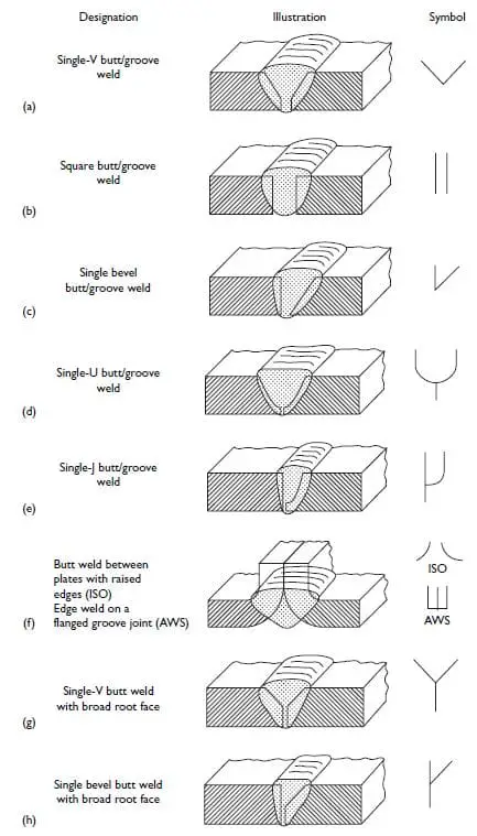
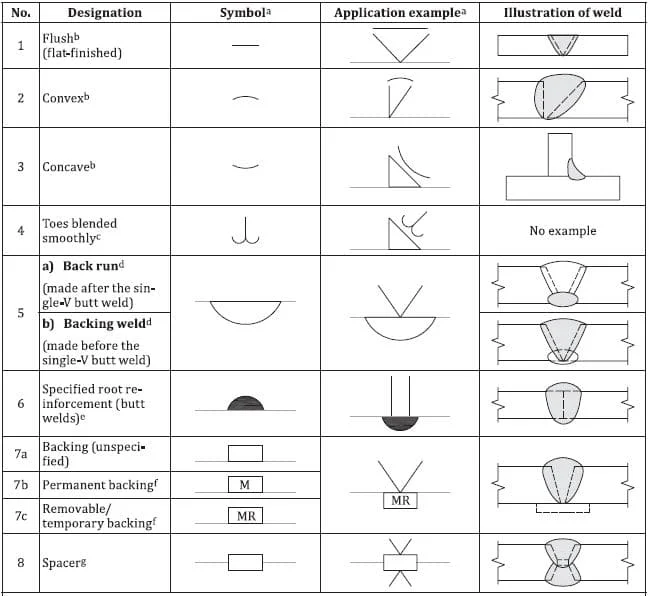
In addition to the elementary welding symbols, ISO 2553 also includes supplementary symbols that provide additional information and specifications related to welding.
These supplementary symbols are used in conjunction with the elementary symbols to convey specific requirements. Here are some examples of supplementary welding symbols defined in ISO 2553:
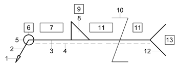
ISO Welding Symbol Tail applications
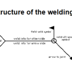
The tail portion of an ISO welding symbol provides additional information about the welding process, acceptance level, working position, and filler materials.
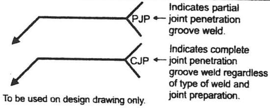
Applications of welding symbol to designate PJP or CJP Weld
Here is the sequence of information typically found in the tail portion:
Process (as per ISO 4063): The first element in the tail portion of the welding symbol often indicates the welding process to be used. ISO 4063 is a standard that classifies various welding and allied processes, such as gas welding, arc welding, resistance welding, etc. The specific process code or abbreviation is usually mentioned to indicate the welding method to be employed.
Acceptance Level (as per ISO 5817 or ISO 10042): The acceptance level refers to the quality requirements for the weld. ISO 5817 and ISO 10042 are standards that define the different levels of weld quality, ranging from flawless appearance (level A) to lower-quality requirements (level D). The acceptance level is indicated to specify the desired quality level of the weld.
Working Position (as per ISO 6947): The working position symbol provides information about the position in which the weld is to be performed. ISO 6947 defines a standard system for representing various welding positions, such as flat position (PA), horizontal position (PB), vertical position (PC), overhead position (PD), etc. The appropriate working position symbol is included to indicate the desired orientation for welding.
Filler Materials (as per ISO 544 or ISO 2560 or ISO 3581): The tail portion may also include information about the filler materials to be used in the welding process. ISO 544, ISO 2560, and ISO 3581 are standards that specify the classification and designation of welding consumables, including electrodes, wires, and rods. The specific code or designation for the filler material is mentioned to indicate the recommended or required consumable for the weld.
By including this information in the tail portion of the welding symbol, it provides additional instructions and requirements for the welding operation, ensuring that the correct welding process, acceptance level, working position, and filler materials are used to achieve the desired results.
Dr. Kumar is a PhD-qualified Welding and Materials Expert with a career spanning 18+ years across metallurgy and NDT. A triple-threat in the industry, he is an IWE, AWS-CWI, and ASNT NDT Level III certified professional. Dr. Kumar is the author of several leading technical resources and is a premier specialist in welding symbol instruction, dedicated to improving global standards in welding engineering and inspection.
Dr. Kumar is a PhD-qualified Welding and Materials Expert with a career spanning 18+ years across metallurgy and NDT. A triple-threat in the industry, he is an IWE, AWS-CWI, and ASNT NDT Level III certified professional. Dr. Kumar is the author of several leading technical resources and is a premier specialist in welding symbol instruction, dedicated to improving global standards in welding engineering and inspection.


 + 7 Practical Examples")

