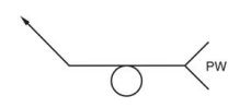
The projection weld symbol shares similarities with the spot weld symbol; however, it distinguishes itself by indicating the use of the projection welding process in the tail of the welding symbol. The weld symbol should …
The projection weld symbol shares similarities with the spot weld symbol; however, it distinguishes itself by indicating the use of the projection welding process in the tail of the welding symbol.
The weld symbol should be positioned above, below, or on the reference line to specify which component bears the projection or embossment, following the location conventions as explained in this article.
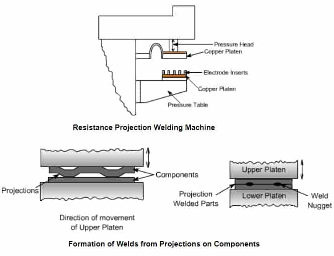
What is a Projection Weld?
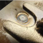
A projection weld is a type of resistance welding process used to join two or more metal components together.
It involves the application of heat and pressure to create a weld at specific points or projections on the surface of the materials.
In a projection weld, the two metal components to be joined are brought into contact with each other, and pressure is applied. An electric current is then passed through the parts at the contact points, generating heat due to resistance.
Projection Weld
As the heat builds up, the material softens and becomes pliable. The pressure applied ensures intimate contact between the surfaces, allowing the heat to melt the metal and form a weld. The electrical current is then stopped, and the pressure is maintained until the weld solidifies.
The projections on the metal surfaces serve as localized areas of increased resistance, concentrating the heat and pressure at specific points.
These projections can take various forms, such as small bumps, studs, or embossments, and they facilitate the efficient transfer of heat and the formation of strong welds.
Projection Weld Symbol
The projection weld symbol is similar to the spot weld symbol, but it incorporates the specific reference to the projection welding process in the tail of the welding symbol.
To indicate which member carries the projection or embossment, the weld symbol should be positioned:
Above,
Below, or
on the reference line, following the location conventions provided below.
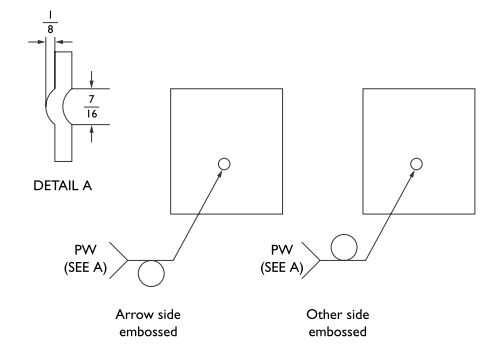
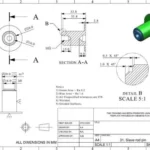
In the ISO system, the letter “P” is used before the weld size to indicate a projection weld, while the AWS standard uses the letters “PW” in the tail of the reference line for the same purpose.
Additionally, the AWS system includes a separate sketch in the symbol’s tail to provide details about the projection’s size. This sketch is shown in Figure above.
These variations ensure clarity and accurate representation of the welding requirements in each standard.
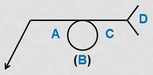
Spacing in a Projection Welds Symbol
The Spacing in a Projection Welds Symbol is always kept on right side of the welding symbol as shown in the below example (location C).
Here in below figure,
A- refers to projection weld size.
B- Quantity of welds.
C- Spacing.
D- Tail to specify Projection weld.
Number Of Projection Welds in a Projection Weld Symbol
The required Number Of Projection Welds for a specific weld joint are kept in parentheses of a Projection Weld Symbol as shown in below figure (Location B).


 + 7 Practical Examples")


