Why Choose the “Skip”?
🌡️ Distortion Control
Perfect for thin materials. By skipping sections, you drastically lower the heat input, preventing that dreaded “potato chip” warping.
💰 Efficiency
Save on filler metal, shielding gas, and labor time. If the code doesn’t require a 100% seal, stitch welding is your best friend.
🏗️ Temporary Fit-up
Essential for tacking large assemblies together before the final pass, ensuring everything stays square and true.
💧 Drainage & Air
Allows moisture to drain and air to escape in non-sealed industrial environments, preventing internal corrosion.
Deep Dive: Reading the Symbols
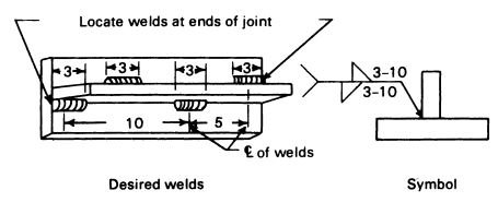
Decoding the “Length – Pitch” Formula
- Length (3): Each individual weld bead must be exactly 3 inches long.
- Pitch (10): The distance from the center of one weld to the center of the next must be 10 inches.
To calculate the actual gap between weld ends, use: Gap = Pitch – Length
Continuous vs. Intermittent: The Comparison
| Feature | Continuous | Stitch (Intermittent) |
|---|---|---|
| Heat Input | High | Low / Controlled |
| Joint Sealing | Hermetic (Air/Water) | Non-Sealing |
| Fabrication Cost | Higher | Lower |
| Visual Inspectability | Direct | Requires Gap Checks |
Types of Stitch Welding Symbols
Stitch Welding Symbols & Classifications
Primary Configurations
Stitch welding symbols vary significantly depending on the joint geometry. In modern fabrication, Stitch Fillet Welds are the most prevalent and are categorized into two critical types:
🔗 Chain Intermittent
Weld segments are perfectly aligned on both sides of the joint, creating a mirrored pattern.
🔀 Staggered Intermittent
Weld segments are offset on opposite sides, creating a zig-zag pattern for different heat distribution.
Master Symbol Reference Table
| S.No | Symbol Type | Welding Symbol Detail | Description / Application |
|---|---|---|---|
| 1 | Intermittent Fillet Weld (Chain) | Fillet weld with length & pitch on same side | Weld segments are aligned on both sides directly opposite each other. |
| 2 | Intermittent Fillet Weld (Staggered) | Fillet weld with staggered indication | Weld segments are offset on opposite sides (zig-zag pattern). |
| 3 | Intermittent Single Side Weld | Fillet weld on one side only with pitch | Used when welding is required on only one side at specific intervals. |
| 4 | Chain Intermittent Weld (Double Side) | Fillet weld both sides aligned | Equal weld segments on both sides in a single straight line. |
| 5 | Staggered Intermittent Weld (Double Side) | Fillet weld both sides staggered | Welds on opposite sides are not aligned, alternating across the joint. |
| 6 | Spot Stitch Weld | Series of spot weld symbols with pitch | Used in resistance welding to indicate specifically spaced weld nuggets. |
| 7 | Seam Stitch Weld | Intermittent seam weld symbol | A continuous weld path broken into discrete segments along a seam. |
| 8 | Back Stitch Weld | Weld segments on reverse side | Used for reinforcement or controlled heat input on the back of the joint. |
| 9 | Intermittent Groove Weld | Groove weld with length & pitch | Applied where a full-depth groove weld is not required continuously. |
| 10 | Intermittent Plug/Slot Weld | Plug/slot weld with spacing | Used for joining overlapping plates at intervals through predefined holes/slots. |
🛠️ Take This Reference to the Shop
Download our high-resolution Stitch Welding Symbols Chart or print it directly for your field handbook.
Source: learnweldingsymbols.com | Professional NDT & Welding Training
Intermittent Fillet Welds Symbols
Intermittent fillet welds are applied in segments rather than as a continuous weld. They are commonly categorized into three types, with the basic form serving as the foundation for the others:
- Basic intermittent fillet welds – used on a single line of weld (see Example 18)
- Staggered intermittent fillet welds – weld segments are offset on opposite sides (see Example 19)
- Chain intermittent fillet welds – weld segments are aligned directly opposite each other (see Example 20)
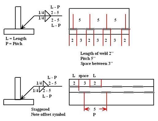
Staggered intermittent fillet welds consist of two parallel lines of intermittent fillet welds placed along a joint. The weld segments in one line are positioned so that they fall between (not directly across from) the weld segments in the opposite line.
Chain intermittent fillet welds, by contrast, also use two parallel lines of intermittent welds, but in this case each weld segment in one line is located directly opposite a weld segment in the other line.
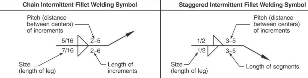
This image illustrates how to read intermittent fillet weld symbols, which are used in engineering drawings to specify welds that are not continuous. These symbols follow the AWS A2.4 standard.
The image is divided into two primary sections: Chain Intermittent and Staggered Intermittent welding.
1. Common Components of the Symbols
In both examples, the numbers located around the triangle (the fillet weld symbol) represent specific dimensions:
- Size (Leg Length): The fraction to the left of the triangle (e.g., 5/16 or 1/2). This indicates the required leg length of the fillet weld.
- Length (L): The first number to the right of the triangle (e.g., 2 or 3). This is the actual length of each individual weld segment.
- Pitch (P): The second number to the right of the triangle (e.g., 6 or 8). This represents the center-to-center distance between the weld segments.
2. Chain Intermittent Fillet Welding (Top)
In a Chain configuration, the fillet weld triangles are placed directly opposite each other on both sides of the reference line.
- Visual Layout: The weld segments on the “arrow side” and the “other side” align perfectly.
- Example interpretation (5/16, 2-6): In 1st Symbol below, You would place a 5/16″ fillet weld segment that is 2″ long, spaced every 6″ (center-to-center), mirrored exactly on both sides of the joint.
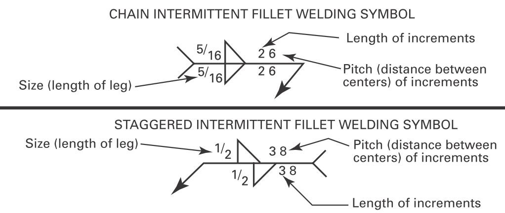
3. Staggered Intermittent Fillet Welding (Bottom)
In a Staggered configuration, the fillet weld triangles are offset from each other on the reference line.
- Visual Layout: The weld segments on one side are placed in the gaps (intervals) of the segments on the opposite side. This creates a “zigzag” pattern of support, which can help reduce distortion in thin materials.
- Example interpretation (1/2, 3-8): In the 2nd figure above, in a Staggered Intermittent Fillet welding symbol, You would place 1/2″ fillet welds that are 3″ long with an 8″ pitch. Because the symbols are offset, the start of the weld on the “other side” begins halfway between the welds on the “arrow side.”
The sketches associated with these types help illustrate the core concept and the rules for their application. In practice, it is generally recommended to keep both the length of each weld segment and the fillet size consistent on both sides of the joint. This approach simplifies fabrication, improves uniformity, and reduces the likelihood of errors during welding.
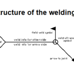
Understanding the Stitch Welding Symbol
The stitch welding symbol is a graphical representation used on engineering drawings to specify the stitch weld pattern required for a particular joint. It consists of several elements that convey essential information to the welder.
Let’s break down the components of the stitch welding symbol:
- Arrow: The stitch welding symbol begins with an arrow, which points to the location where the stitch welds are to be applied. The arrow’s tail is connected to the reference line, indicating the joint to be welded.
- Stitch Length: A number is placed above the reference line, indicating the desired stitch length in millimeters or inches. This value represents the distance between each individual weld in the stitch pattern.
- Stitch Spacing (Pitch): Another number is placed below the reference line, indicating the desired stitch spacing. This value represents the distance between the centers of adjacent stitch welds.
- Stitch Welding Symbol: The stitch welding symbol refers to the type of weld such as Fillet weld or groove weld. A basic weld symbol representing the weld type is placed on the reference line.
Related Topic: Intermittent Fillet Weld Symbols: All types explained
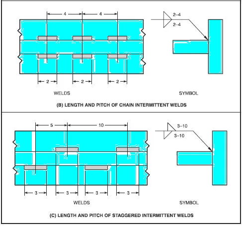
A fundamental rule in intermittent welding is ensuring structural integrity by locating welds at both ends of the joint. The following examples demonstrate how specific symbol notations translate to physical weld patterns on the shop floor.
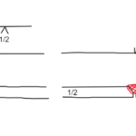
Standard Intermittent Welding
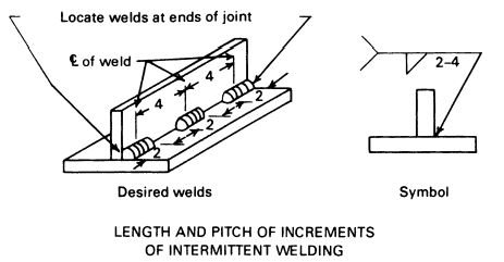
Example A illustrates a single-sided fillet weld using the 2-4 notation.
Chain Intermittent Welding
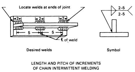
Example B demonstrates a double-sided joint where the welds are perfectly aligned or “mirrored” on both sides of the plate.
Staggered Intermittent Welding
Example C showcases a staggered pattern where the fillet weld triangles are offset on the reference line, indicating a “zig-zag” layout.
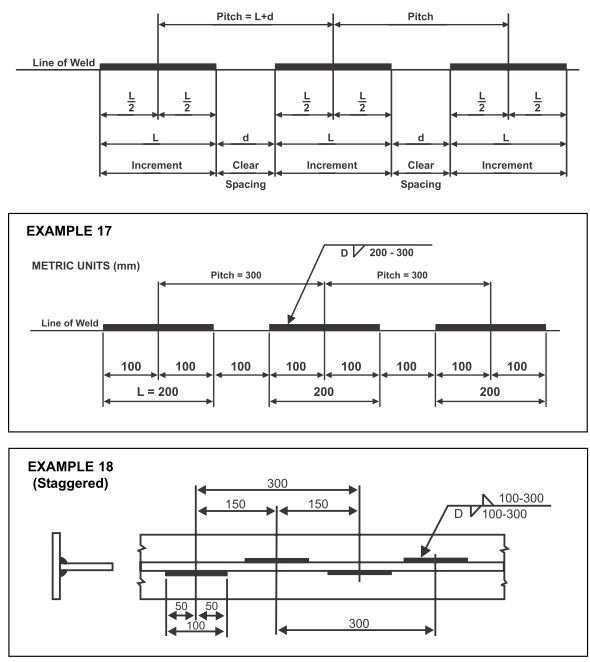
How to Read Stitch Weld Length & Pitch on a Welding Symbol?
On a welding blueprint, stitch (intermittent) dimensions always appear to the right of the symbol. Understanding the relationship between these two numbers is critical for proper joint layout.
Reference: Dimensional layout of intermittent welds on the reference line.
📏 The Length (L)
The first number represents the actual linear length of each weld segment. If the symbol shows 2 – 5, each individual bead must be exactly 2 units long.
🎯 The Pitch (P)
The second number (5 in above example) represents the center-to-center distance between segments. It determines the frequency and distribution of the welds across the joint.
🧠 The “Gap” Calculation
While the blueprint doesn’t explicitly state the size of the “skip” or empty space, you can easily calculate it for your layout:
Gap = Pitch – Length
Example: In a 2-5 weld, your actual gap is 3 units (5 – 2 = 3). Unit can be either mm or inches or cm,anything
🇺🇸 AWS A2.4
The definitive American standard for welding, brazing, and NDT symbols. It mandates the placement of length and pitch dimensions to the right of the weld symbol.
Key Requirement
🌐 ISO 2553
The global standard for symbolic representation of welded joints. ISO 2553 uses two systems (A and B) to accommodate different global traditions in dimensioning.
Key Requirement
(e) for number of elements and utilizes specific line types (dashed vs. solid reference lines) to indicate weld sides.
🇦🇺 AS 1101.3
The Australian standard for graphical symbols in general engineering. It aligns closely with ISO principles while addressing specific regional fabrication practices.
Key Requirement
Conclusion
The stitch welding symbol is a valuable tool for welders, enabling them to accurately interpret and execute stitch welds as per design requirements. By understanding the components of the symbol and their significance, welders can ensure the integrity and quality of the welded joints.
Remember, proper interpretation of welding symbols is crucial for achieving the desired results and maintaining safety standards. So, the next time you come across a stitch welding symbol on an engineering drawing, you’ll be well-equipped to tackle the task at hand.
Stitch Welding: Technical FAQ
What is the stitch welding symbol?
How do you read stitch length and pitch?
L - P.
- Length (L): The first number, representing the actual linear length of each individual weld segment.
- Pitch (P): The second number, representing the center-to-center distance between adjacent weld segments.
2 - 5 indicates 2-inch long welds spaced 5 inches apart from center to center.
What is the difference between stitch welding and intermittent welding?
What is the AWS standard for stitch welding?
When should stitch welding be used?
- Distortion Control: To limit total heat input and prevent warping in thin materials.
- Weight & Material Savings: When the structural load does not require a 100% continuous weld.
- Cost Efficiency: To reduce filler metal consumption and labor time.
- Ventilation/Drainage: In non-sealed joints where moisture drainage or air expansion is necessary.
About Me

Dr. Kumar is a PhD-qualified Welding and Materials Expert with a career spanning 18+ years across metallurgy and NDT. A triple-threat in the industry, he is an IWE, AWS-CWI, and ASNT NDT Level III certified professional. Dr. Kumar is the author of several leading technical resources and is a premier specialist in welding symbol instruction, dedicated to improving global standards in welding engineering and inspection.