Welding symbols are vital for effective communication in engineering and manufacturing industries. They provide a standardized visual representation of welding processes and specifications on engineering drawings. Among the various welding symbols, the single fillet weld …
Welding symbols are vital for effective communication in engineering and manufacturing industries. They provide a standardized visual representation of welding processes and specifications on engineering drawings.
Among the various welding symbols, the single fillet weld symbol holds significant importance. In this article, we will explore & learn the details of the single fillet weld symbol, its components, and its application in engineering.
Overview of the Single Fillet Weld Symbol
The single fillet weld symbol is used to represent a specific type of weld joint known as a fillet weld.
Fillet welds are commonly used to join two components or parts that meet at an angle, typically a right angle. The single fillet weld symbol provides important information about the size, length, and other specifications of the fillet weld.
Components of the Single Fillet Weld Symbol
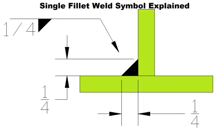
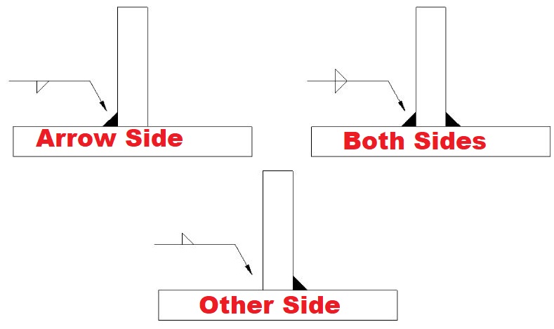
A single Fillet Weld Symbol is shown in the below example. A single fillet weld symbol consists of triangle placed on the reference line. Based on the placement, arrow side or other side of the weld is considered as explained in below figure.
The length of the fillet weld is always given on the left side of the weld symbol. In the below example, 1/4-inch weld size means a leg length of 1/4-inch is required for the fillet weld as per this welding symbol.
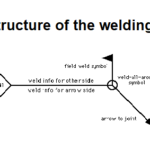
The main parts of a Single Fillet Welding Symbol are:
Reference Line: The reference line is the base line of the welding symbol, and the fillet weld symbol is attached to it. The arrow or other elements indicating the joint location are also placed on the reference line.
Arrow: The arrow points to the location where the fillet weld is to be made. It indicates the side of the joint where the weld is applied.
Weld Size: The size of the fillet weld is indicated to the left of the reference line. It represents the leg length of the weld, which determines the size and strength of the joint.
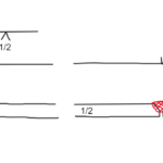
Length Dimension: The length of the fillet weld is specified to the right of the reference line (not shown in above example). It provides information about the extent or distance over which the weld should be applied.
The single fillet weld symbol is commonly used in engineering drawings to specify the requirements for fillet welds in various applications.
It ensures clear communication between designers, engineers, and welders, allowing them to understand the welding specifications accurately.
Parts of the single fillet weld
Weld Size: The size of the fillet weld determines its strength and load-bearing capacity. The symbol provides clear instructions on the required leg length of the fillet weld.
Length of Weld: The length dimension specified by the symbol indicates the distance over which the fillet weld should be applied. It ensures consistency and uniformity in the welding process.
Joint Configuration: The single fillet weld symbol also conveys the joint configuration, indicating that a fillet weld is required for the specific joint angle.
Dr. Kumar is a PhD-qualified Welding and Materials Expert with a career spanning 18+ years across metallurgy and NDT. A triple-threat in the industry, he is an IWE, AWS-CWI, and ASNT NDT Level III certified professional. Dr. Kumar is the author of several leading technical resources and is a premier specialist in welding symbol instruction, dedicated to improving global standards in welding engineering and inspection.
Dr. Kumar is a PhD-qualified Welding and Materials Expert with a career spanning 18+ years across metallurgy and NDT. A triple-threat in the industry, he is an IWE, AWS-CWI, and ASNT NDT Level III certified professional. Dr. Kumar is the author of several leading technical resources and is a premier specialist in welding symbol instruction, dedicated to improving global standards in welding engineering and inspection.


 + 7 Practical Examples")


