Groove Welding Symbols
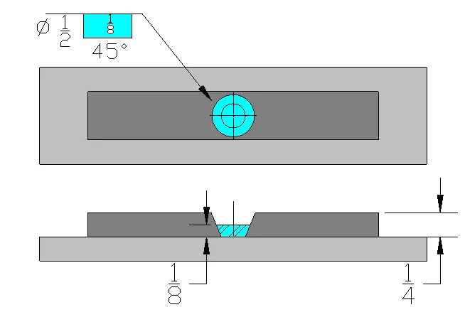
To convey the necessary information about a groove weld when parts are welded in same plane. A Groove welding symbol may contain various details, such as the symbol for the groove weld itself, its size, the depth of preparation, the root opening, the angle of the groove (also known as the included angle), the contour, the method used to create the contour, the length, the pitch, whether the weld is all around or a field weld, and any additional relevant information listed in the tail of the welding symbol.
Groove welding is a type of welding that involves joining two pieces of metal together at their edges or “grooves.” Groove weld joint is commonly used in the manufacturing, construction, and fabrication industries, where it is often necessary to produce sound and high strength welding joints between metal components.
To ensure that these joints are created correctly to meet their intended applications, welding symbols are used to communicate important information about the weld size, weld location and correct welding process (optional). In this article, we will discuss groove welding symbols, what they mean and how to correctly read & interpret them.
Types of Groove Welding Symbols
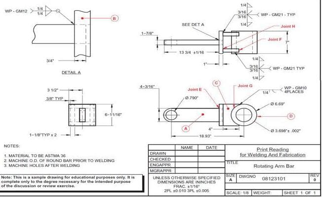
Groove welding symbols are used to specify the type of groove that is to be welded, its location, weld size and other additional information’s. These symbols are typically included on engineering drawings and blueprints, which are used by welders to guide their work. The symbols consist of a arrow line, reference line, weld symbol and tail (optional) that represent the shape of the groove and the weld location.
There are several types of groove welding symbols, including:
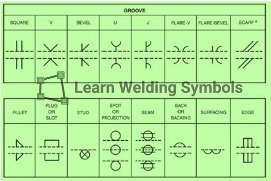
- Square Groove Symbols
- Bevel Groove Symbols (Single Bevel & Double Bevel Groove weld symbol)
- V-Groove Symbols (Single V & Double V-Groove weld symbol)
- U-Groove Symbols (Single U & Double U-Groove weld symbol)
- J-Groove Symbols (Single J & Double J-Groove weld symbol)
- Flare Bevel-Groove Symbols
- Flare Bevel V-Groove Symbols
The welding symbol of these groove types are almost identical to the actual shape of the weld grooves as shown in below figure. When a weld is intended to be applied to just one side of a joint, it is referred to as a single groove weld.
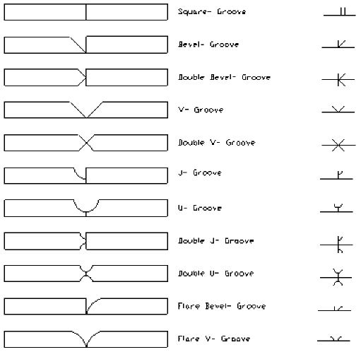
For instance, the welding symbol below depicts a single V-Groove weld on the opposite side. It is generally assumed that all single groove welds are complete joint penetration (CJP) unless stated otherwise.
Each of these symbols represents a different type of groove that is to be welded, and each symbol has its own unique set of specifications.
Square Groove Symbols
The square groove symbol is used to indicate a square or rectangular groove that is to be welded. This symbol consists of two parallel lines that are perpendicular to the weld line. The depth of the groove is indicated by a number that is placed on left side of this weld symbol.
V-Groove Symbols
The V-groove symbol is used to indicate a V-shaped groove that is to be welded. This symbol consists of a two lines that is angled at 45 degrees to the reference line. The depth of the groove is indicated by a number that is placed on the left side of this V-shape weld symbol.
U-Groove Symbols
The U-groove symbol is used to indicate a U-shaped groove that is to be welded. This symbol consists of a single line that is curved to indicate the shape of the U groove.
J-Groove Symbols
The J-groove symbol is used to indicate a J-shaped groove that is to be welded. This symbol consists of a single line that is curved to indicate the J-shape of the groove, with a small horizontal line at the bottom to indicate the depth of the groove.
Flare Bevel Groove
A flare bevel groove is a type of groove used in welding that features a beveled edge having a radius profile on one of the parts to be joined. The bevel creates a V-shaped groove that widens towards the base metal. This wider groove allows for the weld metal to penetrate deeper into the joint.
Welding Process Symbols
In addition to the groove symbols, there are also symbols that indicate the welding process that should be used. These symbols include the letters “FCAW” for flux-cored arc welding, “GMAW” for gas metal arc welding, and “SMAW” for shielded metal arc welding.
Groove weld dimensioning & size
If necessary, several dimensions may be added to a groove weld, such as the:
- Groove angle,
- root opening,
- groove radius,
- depth of the groove preparation, and
- groove weld size.
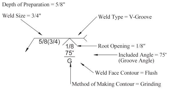
However, there may be instances where this information is not included at all. In such cases, it is left to the discretion of the welder to determine how the part will be prepared and welded.
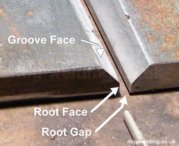
The groove angle is typically shown in degrees and encompasses the entire groove. For a V Groove, it is a dimension from one groove face to the other. It is important to note that the groove angle should not be confused with the bevel angle, which is only half the angle of a V groove. The dimension for groove angle is indicated within the weld symbol itself. If applying to a double groove weld, there is a possibility for two different angles. It is worth noting that the arrow and the other side do not have to match in terms of angles.
Conclusion
It is important for welders to understand groove welding symbols and what they mean in order to ensure that they are performing the correct welding process and creating strong and durable joints. By following the specifications indicated by the symbols on the engineering drawings, welders can produce high-quality work that meets the requirements of their clients and customers.
