Contour Welding Symbols Contour welding symbols are essential for conveying specific information about the desired shape or profile of a weld. Knowing how to read and interpret these symbols is crucial for welders, inspectors, and …
Contour welding symbols are essential for conveying specific information about the desired shape or profile of a weld. Knowing how to read and interpret these symbols is crucial for welders, inspectors, and engineers to ensure the correct application of welding techniques and achieve the desired results. In this article, we will learn what is contour welding & different contour welding symbols, and their application in the welding.
Contour welding symbols are graphical representations that indicate the desired shape or profile of a weld bead. They provide critical information about the weld’s geometry, helping welders understand how to apply the welding technique to achieve the desired contour.
Contour symbols are used in conjunction with other welding symbols on engineering drawings and welding procedure specifications (WPS) to convey complete information about weld requirements.
Note: Contour Weld symbols are Supplementary weld symbols and are placed along with Basic Weld Symbols.
Types of Contour Welding Symbols
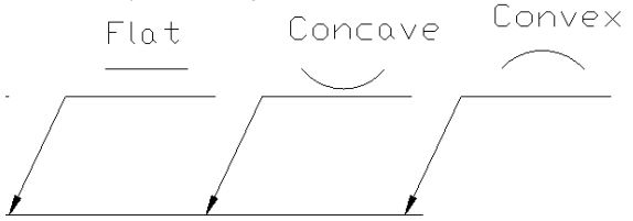
There are three primary types of contour welding symbols:
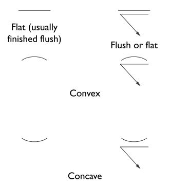
Flat Contour: A flat contour symbol or also called Flush Contour indicates that the weld should be finished with a flat or nearly flat surface. This contour is often used when the weld needs to blend smoothly with the surrounding base material. The symbol for a flat contour is a straight horizontal line.
Convex Contour: A convex contour symbol signifies that the weld should be finished with a surface that curves outward, creating a convex shape. This type of contour is commonly used when additional reinforcement is needed, such as in fillet welds. The symbol for a convex contour is a curved line that arches upward.
Concave Contour: A concave contour symbol indicates that the weld should be finished with a surface that curves inward, forming a concave shape. This contour is often used when there are concerns about weld shrinkage or to minimize stress concentrations. The symbol for a concave contour is a curved line that arches downward.
ISO contour weld symbols are similar to AWS A2.4 except ISO contour weld symbols has additional contour symbol for Toes Blended smoothly as shown in below figure.
Using Contour Welding Symbols
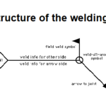
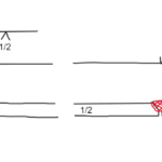
Contour welding symbols are typically displayed above or below the reference line on a welding symbol, depending on whether the contour applies to the arrow side or other side of the joint. They may also appear in the tail of the welding symbol if additional instructions or information is required.
For example, a weld symbol with a convex contour on the arrow side would have the contour symbol above the reference line, while a weld symbol with a concave contour on the other side would have the contour symbol below the reference line.
In some cases, a finishing method may also be specified alongside the contour symbol, indicating the preferred technique for achieving the desired contour. Common finishing methods include grinding (G), machining (M), chipping (C), or hammering (H).
Why are Contour Welding Symbols Important?
Contour welding symbols play a crucial role in the welding industry for several reasons:
Clear Communication: They provide a standardized means of conveying information about the desired weld contour, ensuring that welders, inspectors, and engineers are on the same page.
Quality Control: Contour symbols help maintain consistency in the welding process, ensuring that the finished weld meets design requirements and specifications.
Enhanced Aesthetics: Properly executed contours can improve the appearance of the finished weld, making it blend more seamlessly with the surrounding base material.
Structural Integrity: Contours can affect the strength and durability of a weld, so it’s essential to apply the correct contour to meet structural requirements and minimize potential weaknesses.
Understanding contour welding symbols is vital for welders, inspectors, and engineers to ensure the proper execution of welding techniques and achieve the desired results. By familiarizing yourself with the three primary types of contour symbols and their applications, you can enhance your ability to interpret welding symbols and contribute to the overall success of your welding job.
Dr. Kumar is a PhD-qualified Welding and Materials Expert with a career spanning 18+ years across metallurgy and NDT. A triple-threat in the industry, he is an IWE, AWS-CWI, and ASNT NDT Level III certified professional. Dr. Kumar is the author of several leading technical resources and is a premier specialist in welding symbol instruction, dedicated to improving global standards in welding engineering and inspection.
Dr. Kumar is a PhD-qualified Welding and Materials Expert with a career spanning 18+ years across metallurgy and NDT. A triple-threat in the industry, he is an IWE, AWS-CWI, and ASNT NDT Level III certified professional. Dr. Kumar is the author of several leading technical resources and is a premier specialist in welding symbol instruction, dedicated to improving global standards in welding engineering and inspection.