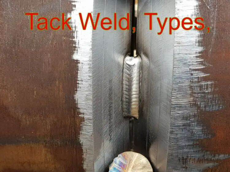
What is a chamfer weld?
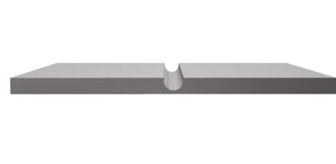
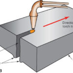
A chamfer weld refers to a type of weld joint configuration where the edges of the workpieces are chamfered or beveled before welding. Chamfering involves cutting or grinding the edges of the workpieces at an angle, typically in a V-shape or U-shape, to create a groove or recess.
The chamfered edges provide a larger welding surface area and allow for better penetration and fusion during the welding process.
Chamfer welds are commonly used in various welding applications, including butt joints, corner joints, and T-joints. They are particularly beneficial when joining thicker materials or materials with different thicknesses, as the chamfer helps to ensure proper weld penetration and strength.
How is chamfering indicated in a welding symbol?
Chamfering, which refers to the process of beveling or sloping the edges of a workpiece, can be indicated in a welding symbol using specific notations.
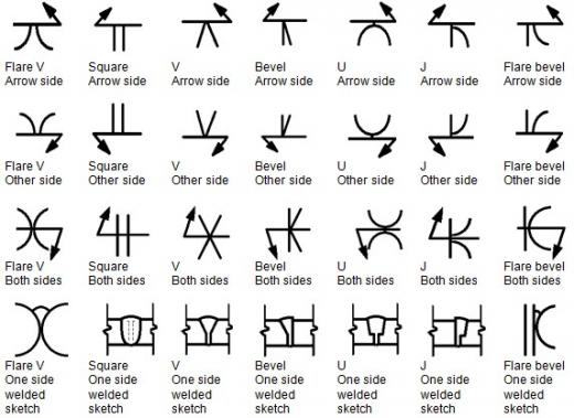
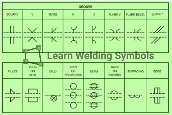
The most common way to represent chamfering in a welding symbol is by adding a specific type weld symbol to the reference line of the symbol. The common chamfering symbols are:

Machining Chamfering callout
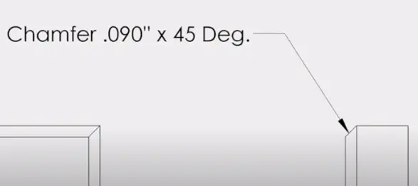
The term “chamfer” refers to a slanted or sloped surface at the edge of a component. When it comes to drawings, a chamfer callout indicates how to specify the dimensions of chamfers.
Chamfers are typically used to remove sharp edges and facilitate the assembly of closely fitting parts. In this article, we will explore the correct method for making a chamfer callout and provide guidance on how to do so in popular software programs.
Properly specifying a chamfer feature is crucial when dimensioning drawings, particularly for establishing tolerances for the components within an assembly. While there are various ways to accomplish this, there are commonly accepted approaches, including:
- Utilizing the length and angle of the chamfer (e.g., 0.09″ x 45°) as per the ASME Y14.5M standard.
Bevel angle chamfering symbol
The bevel angle for chamfering in a welding symbol is typically indicated by a number placed in the middle of the reference line of the symbol. The number represents the angle of the chamfer, measured in degrees.
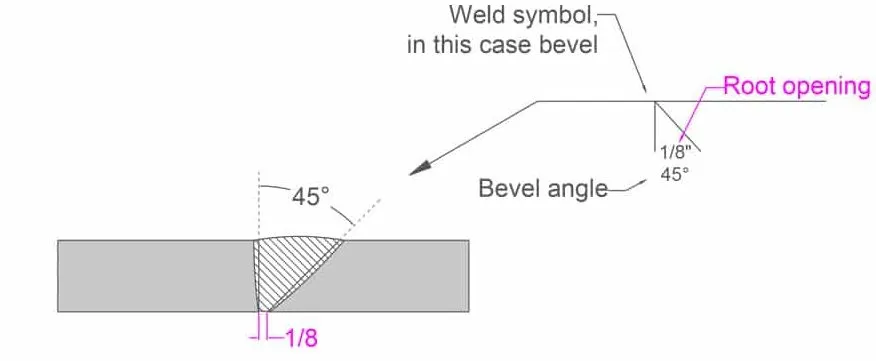
To indicate a bevel angle chamfer, the number is written above a horizontal line that intersects the reference line. The horizontal line represents the length of the chamfered area. The bevel angle is written as a numerical value, such as “30” or “45,” indicating the angle of the chamfer.
V Groove chamfering symbol
The V groove chamfering symbol in a welding symbol is represented by a V-shaped symbol placed above the reference line. The V groove indicates that the edges of the workpiece should be chamfered or beveled in a V shape before welding.
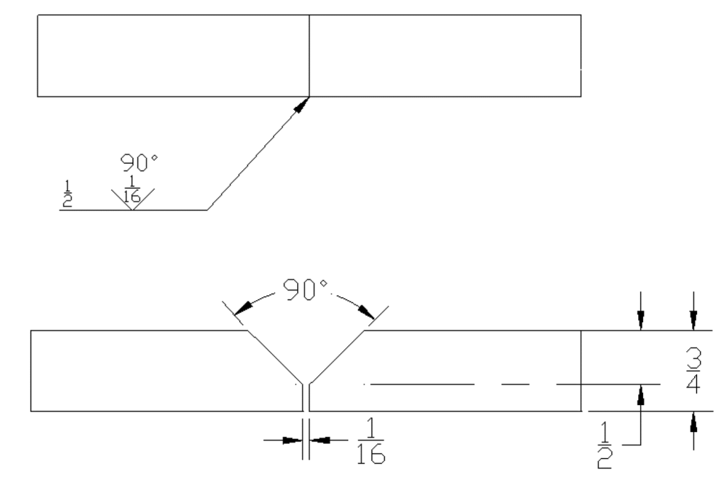
The V groove chamfering symbol may also include additional specifications to provide further details about the chamfer, such as the angle and depth.
J-Groove chamfering symbol
The J groove chamfering symbol in a welding symbol is represented by a J-shaped symbol placed above the reference line. The J groove indicates that the edges of the workpiece should be chamfered or beveled in a J shape before welding.
The J groove chamfering symbol may also include additional specifications to provide further details about the chamfer, such as the angle and depth.
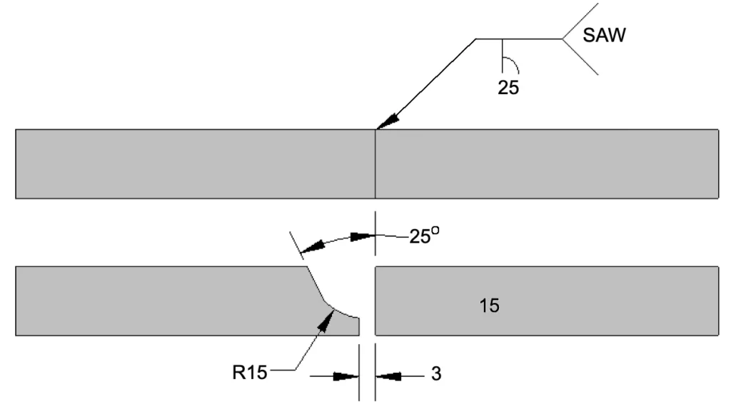
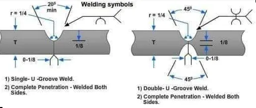
U-Groove chamfering symbol
The U groove chamfering symbol in a welding symbol is represented by a U-shaped symbol placed above the reference line. The U groove indicates that the edges of the workpiece should be chamfered or beveled in a U shape before welding.
Similar to other chamfering symbols, the U groove chamfering symbol may include additional specifications to provide further details about the chamfer, such as the angle and depth.
