When it comes to welding, one of the critical factors that can influence the strength and integrity of the joint is the size of the fillet weld. Understanding how to determine the optimal fillet weld …
Written by: Sandeep Kumar
Published on:
When it comes to welding, one of the critical factors that can influence the strength and integrity of the joint is the size of the fillet weld. Understanding how to determine the optimal fillet weld size is essential for achieving reliable and effective welds. In this post, we will explore the thumb rule for calculating fillet weld sizes and the considerations involved.
Why Fillet Weld Size Matters
Fillet welds are commonly used in various applications, from structural to fabrication projects. The right size ensures that the weld can withstand the maximum stresses without wasting materials or incurring unnecessary costs. A weld that is too large may not provide additional strength but can lead to increased labor and material expenses.
Calculating Fillet Weld Size
Minimum and Maximum Size
To determine the minimum and maximum size of a fillet weld, follow these guidelines:
Minimum Size: The leg length of the fillet weld should be at least 0.75 times the material thickness. For instance, if the material thickness is 10 mm, the minimum fillet size should be 7 mm.
Maximum Size: Any weld size larger than what is determined by the calculation typically does not add strength but may lead to wastage of resources.
In cases where two plates of different thicknesses are being welded, it is advisable to base the weld size on the thinner member. This approach helps ensure that the joint can effectively handle the stresses without compromising integrity.
Example Calculation
Suppose you are welding two plates, one with a thickness of 0.5 inches and the other with a thickness of 0.375 inches. The leg length (z) of the fillet weld can be calculated as follows:
For the thicker plate (0.5 inches), the minimum weld size would be 0.75×0.5=0.3750.75×0.5=0.375 inches.
For the thinner plate (0.375 inches), the minimum weld size would be 0.75×0.375=0.281250.75×0.375=0.28125 inches.
In this scenario, you would choose the larger of the two calculations to ensure strength.
AWS Recommendations
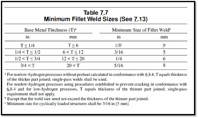
The American Welding Society (AWS) provides guidelines for minimum fillet weld sizes in standards such as AWS D1.1. According to AWS, the sizes are specified in terms of leg length rather than throat size, aligning with standard practices in the USA.
You can refer below table for minimum fillet weld size required as per AWS D1.1 depending on the material thickness.
Throat Size (a) to Leg Length (Z) Conversion Formula
Understanding the relationship between throat size and leg length is essential for accurate weld specifications. The throat size (a) refers to the shortest distance from the root of the weld to the face of the weld, while the leg length (z) is the distance from the edge of the base material to the toe of the weld.
For a fillet weld with equal leg lengths, the cross-section forms a right-angled triangle where the angles are 45 degrees. This geometry allows us to establish a relationship between the throat size and the leg length based on simple trigonometric principles.
Conversion Formulas
The relationship between throat size (a) and leg length (z) can be expressed with the following formulas:
From Leg Length to Throat Size:a≈0.7za≈0.7z
From Throat Size to Leg Length:z≈1.4az≈1.4a
These formulas indicate that:
The throat size is approximately 70% of the leg length.
Conversely, the leg length is approximately 140% of the throat size.
Mathematical Insight
For those interested in the mathematical basis behind these ratios:
The factor of 0.7 can be approximated as 1221.
The factor of 1.4 can be approximated as 22.
Practical Application
When designing a weld, it’s crucial to ensure that both the throat size and leg length are appropriately specified to meet the load requirements. Using these conversion formulas allows welders and engineers to efficiently switch between measurements based on project specifications or design requirements.