Blueprint symbols play a crucial role in the world of machining, enabling effective communication between engineers, machinists, and manufacturers. These symbols serve as a universal language, providing precise instructions and specifications for the production of complex machined parts.
In this blog post, we will delve into the world of machining blueprint symbols, uncovering their meanings and significance in the manufacturing process.
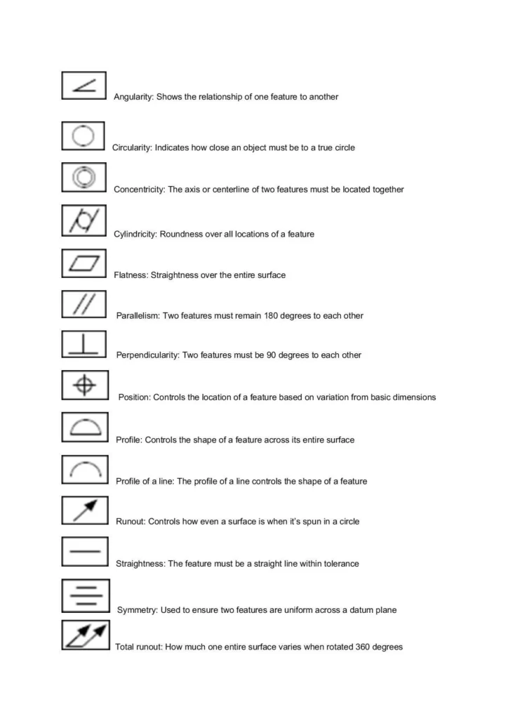
Geometric Dimensioning and Tolerancing (GD&T) Symbols
GD&T symbols are used to define and communicate tolerances, dimensions, and geometric features on a machined part.
Some commonly used GD&T symbols include:
Diameter Symbol (⌀): Indicates the diameter of a cylindrical feature.
Concentricity Symbol (⌖): Specifies the condition where two or more features share a common center axis.
Perpendicularity Symbol (⊥): Represents a 90-degree relationship between two surfaces or features.
Position Symbol (⌖): Defines the allowable deviation from a specified position for a feature.
Parallelism Symbol (‖): Indicates that two surfaces or features must be parallel to each other.
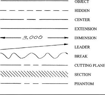
What Information Can You Obtain from the Various Lines on a Blueprint?
The lines found on a blueprint serve as the universal language through which information is conveyed. They play a crucial role in communicating the details required by craftsmen to create, assemble, service, or inspect a product, part, or component.
Each line possesses its own characteristics, such as weight (thickness) and form, which, when combined with other features, provide skilled workers with the necessary information to interpret the drawing accurately.
Outlined below are descriptions of the most commonly encountered lines on blueprints, shedding light on their purposes:
Visible line: This thick, continuous line outlines the edges or contours of an object, making it clearly visible on the drawing.
Hidden line: Represented by a series of short dashes approximately 1/8″ long with 1/16″ gaps, hidden lines depict edges, surfaces, and corners that are not directly visible. They help convey information about features that are concealed from view.
Centerline: Typically a very thin, long-short-long line, the centerline is used to indicate the centers of holes, arcs, or symmetrical objects. It serves as a reference for aligning or positioning other elements.
Dimension and extension lines: The dimension line is a thin, solid line that specifies the size of an object. Arrowheads are placed at each end of the dimension line to indicate where it connects to the extension lines.
Short and long break lines: Break lines are employed to remove sections of a drawing for clarity or to shorten objects that don’t fit within the available space. They indicate that a portion of the object is not shown in the drawing.
Phantom line: Phantom lines consist of thin, long-short-short-long segments. They are used to depict the movement of an object, display parts in alternate positions, or indicate the presence of adjacent objects or features.
Cutting plane line: These heavy lines slice through the object and provide a view of its internal shape or structure. Cutting plane lines are useful for revealing hidden details within the part.
Section line: In section views, angled thin lines known as section lines are employed to indicate cut surfaces. They provide a visual representation of what the object would look like if it were cut and viewed from a specific angle.
Leader line: Leader lines are thin lines drawn at a 45-degree angle that point to specific elements on the drawing, requiring clarification or additional information.
Surface Texture Symbols
Surface texture symbols are used to communicate the desired surface finish and texture of machined surfaces. These symbols provide information about parameters such as roughness, waviness, and lay patterns. Common surface texture symbols include:
Roughness Symbol (Ra): Represents the average surface roughness value.
Waviness Symbol (Wt): Indicates the allowable deviation from a specified waviness pattern.
Lay Symbol (↓): Specifies the direction of surface texture features, such as machining marks or grain orientation.
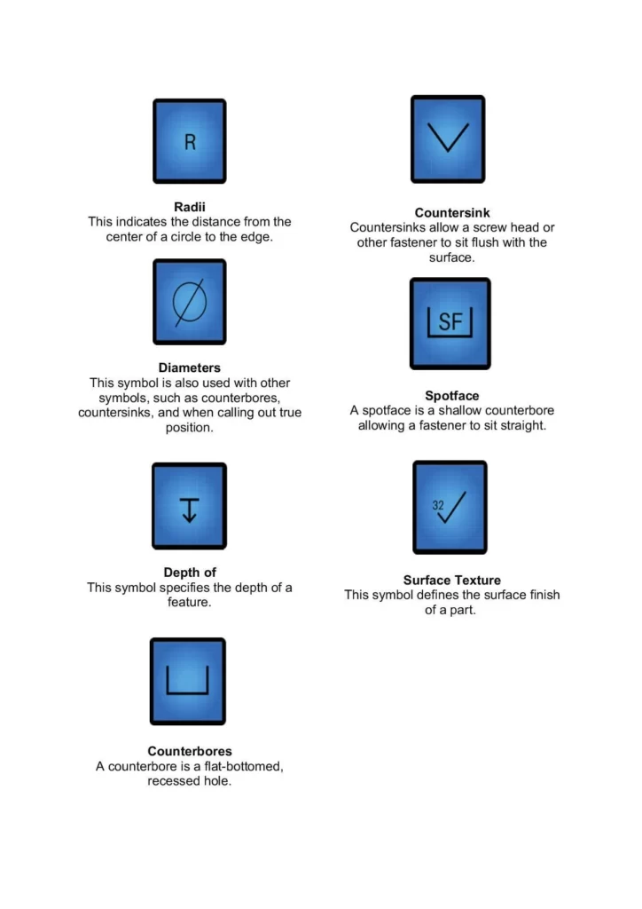
Radii: Radii refer to the rounded edges or curves on a machined part. They are represented on blueprints using a specific symbol, often denoted as an arc with a center point, indicating the desired radius dimension.
Countersink: Countersinking is a machining process that involves creating a conical-shaped recess on the surface of a part to accommodate the head of a screw or bolt. The countersink symbol on a blueprint typically consists of a circle with a diagonal line indicating the angle of the countersink.
Diameters: Diameters represent the width of a circular feature, such as a hole or a cylindrical component. They are usually indicated by a diameter symbol (⌀) followed by the value of the diameter.
Spotface: A spotface is a flat machined surface created to provide a smooth and level base for a washer or bearing. It is represented on blueprints by a symbol consisting of a circle with a shaded interior.
Depth of: The depth of a feature refers to the measurement from the surface of a part to the bottom of a hole, groove, or recess. It is typically indicated by a horizontal line with an arrow pointing down and a dimension value specifying the depth.
Surface texture: Surface texture refers to the characteristics of a machined surface, such as its roughness, waviness, or pattern. On blueprints, surface texture symbols are used to communicate the desired surface finish. They can include symbols such as Ra (average roughness), Wt (waviness), and various other symbols representing different surface texture parameters.
Counterbore: A counterbore is a cylindrical recess created at the top of a hole to accommodate the head of a screw or bolt. It allows the fastener to sit flush with or below the surface of the material. Counterbores are indicated on blueprints using a symbol consisting of a circle with a larger diameter than the hole, along with depth and diameter dimensions.
Machining Process Symbols
Machining process symbols are used to indicate specific machining operations to be performed on a part. These symbols help convey critical information regarding the required processes and techniques. Some examples include:
Turning Symbol (↻): Indicates that the part needs to be machined using a lathe or turning operation.
Milling Symbol (⊕): Represents a milling operation, typically performed using a milling machine.
Drilling Symbol (⊗): Indicates the need for a drilling operation to create holes in the part.
Grinding Symbol (☢): Represents a grinding process used for precision finishing or shaping.
Feature Control Frames
Feature control frames are used to specify the geometric tolerances and related dimensions of specific features on a machined part. They provide a structured way to communicate the required tolerances for features such as holes, slots, and surfaces.
Conclusion
Understanding machining blueprint symbols is essential for effective communication and successful manufacturing processes. By comprehending the meanings and applications of these symbols, engineers, machinists, and manufacturers can collaborate seamlessly, ensuring accurate and precise production of machined parts.
Whether it’s GD&T symbols, surface texture symbols, or machining process symbols, each symbol serves a specific purpose in conveying vital information about dimensions, tolerances, surface finishes, and machining operations.


: A Comprehensive Guide")


