The basic structure of brazing symbols closely resembles that of welding symbols. The gap between the components can be indicated in a similar fashion to how root openings are specified in welding symbols.
Brazing is a widely used metal joining process that offers numerous benefits, including strong and durable connections between different components.
Just like welding, brazing also utilizes symbols to communicate important information about joint design and specifications.
In this blog post, we will learn the brazing symbols, exploring their significance and how they contribute to successful brazed joints.
The Purpose of Brazing Symbols
Brazing symbols serve as a visual language for engineers, designers, and fabricators to effectively communicate the requirements for brazed joints.
These symbols provide crucial information about joint design, clearance, and other essential dimensions, ensuring that the brazing process is carried out accurately and consistently.
Letter Designation for Brazing Process using Brazing Symbol
The table below presents the letter designations for different brazing processes commonly used in construction:
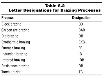
Table: Brazing Processes and Letter Designations
Basic Structure of Brazing Symbols
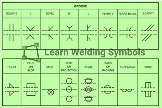
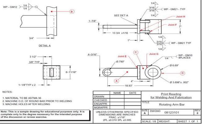
Brazing symbols follow a standardized format similar to welding symbols. They consist of various elements, including reference lines, arrow, and specific geometric shapes, each carrying a distinct meaning. Understanding these elements will enable professionals to interpret and apply brazing symbols correctly.
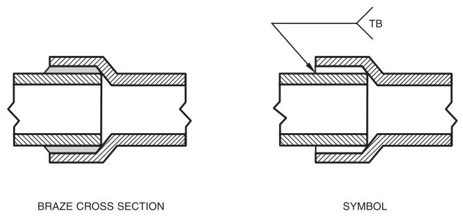
When a brazed joint requires no special preparation other than cleaning, the arrow and reference line are used in conjunction with the brazing process designation placed in the tail of the symbol.
In Figure below, a sketch and corresponding symbol depict a brazed socket joint.
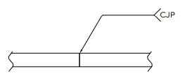
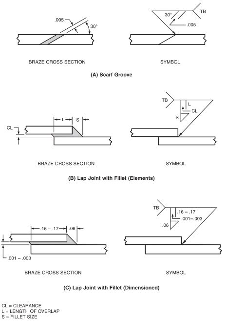
Furthermore, conventional weld symbols can be applied to brazed joints, as shown in Figures 8.37(A) through 8.37(F).
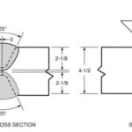
Figure 8.37(A) illustrates the desired scarf configuration and dimensions of a brazed joint on the left, accompanied by the corresponding brazing symbol on the right.
Additionally, Figure 8.37(A) demonstrates the method of specifying a scarf angle.
Figures 8.37(A), (B), (C), (D), and (F) exemplify how joint clearance dimensions can be incorporated into a brazing symbol.
Indicating Clearance and Gap
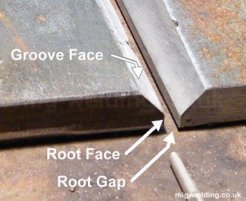
One important aspect of brazing symbols is specifying the clearance or gap between the components being joined. This clearance ensures the proper flow and distribution of the brazing filler material.
Brazing symbols use specific notations and dimensions to indicate the required clearance, similar to how root openings are conveyed in welding symbols. Proper clearance ensures optimal capillary action and ultimately results in strong, void-free joints.
Joint Design Considerations
Brazing symbols also provide valuable information about joint design considerations. They may indicate the type of joint, such as lap joint, butt joint, or T-joint, and the specific orientation of the components.
Additionally, symbols may include supplementary information about pre-brazing operations, such as surface preparation, flux application, and joint alignment.
Understanding Material Specifications
Brazing symbols can also convey material specifications, such as the type of base metal and brazing filler material to be used.
These specifications play a vital role in achieving a successful brazed joint with the desired mechanical properties and performance.
Importance of Standardization
Standardization of brazing symbols is essential to ensure clear and consistent communication throughout the manufacturing and fabrication process.
Following established standards, such as those set by the American Welding Society (AWS A2.4) or the International Organization for Standardization (ISO 2553), helps prevent misinterpretation and promotes efficient collaboration among different stakeholders.
