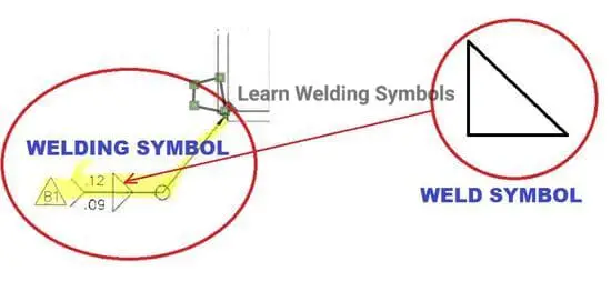
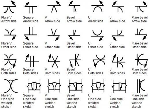
Weld symbols are graphical representations used in engineering and construction to convey vital information about weld joints and their characteristics. These symbols play a crucial role in ensuring accurate communication and understanding between designers, fabricators, and welders.
In this blog post, I have covered the concepts of symmetrical and non-symmetrical weld symbols, exploring their significance and application in welding processes as per AWS A2.4 specification for welding symbols.
Symmetrical Weld Symbols
Symmetrical weld symbols are used when both sides of the reference line possess axes of symmetry that are perpendicular to the reference line. In simpler terms, the weld symbols on either side of the reference line are mirror images of each other.

When using symmetrical weld symbols, it is essential to align the axes of the symbols directly across the reference line. This alignment enhances clarity and aids in the interpretation of the welding specifications.
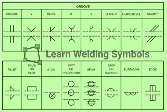
Common weld symbol which can be Symmetrical Weld Symbols are:
- Fillet weld on both sides,
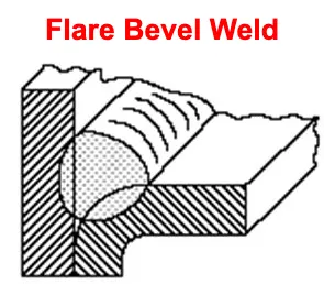
- Flare Bevel on both sides,
- Double V-groove weld
- J groove on both sides,
- U-Groove on both sides,
- Square groove,
- Flare Bevel and Flare Groove weld.
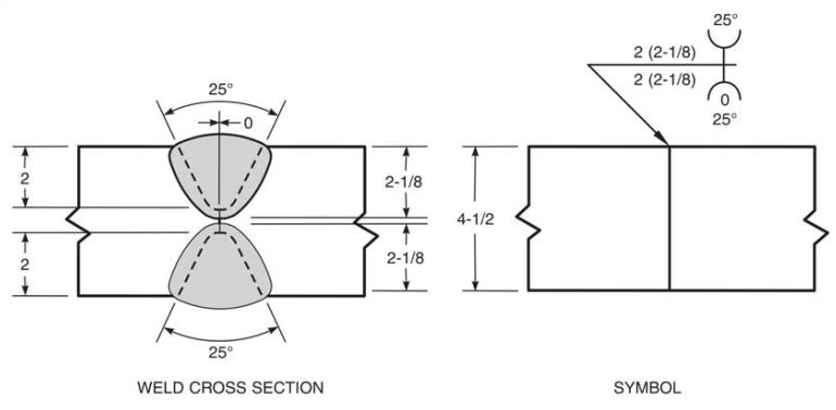
Symmetrical weld symbols are commonly employed in various welding applications, and they promote visual consistency and ease of understanding. By aligning the symmetrical weld symbols, welders can quickly identify the joint configuration, welding process, weld size, and other critical parameters.
Non-Symmetrical Weld Symbols
Non-symmetrical weld symbols, as the name suggests, lack an axis of symmetry perpendicular to the reference line. In such cases, the leftmost points where the symbols make contact with the reference line should be aligned.
This alignment ensures that the weld symbols are positioned consistently, even if they do not possess mirror-like symmetry.

Non-symmetrical weld symbols are employed when the joint configuration or welding requirements do not allow for symmetrical representation. These symbols may indicate specific details related to the weld joint, such as the presence of fillet welds, groove welds, or other complex welding configurations.
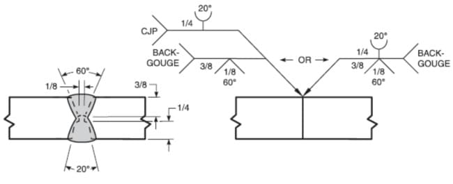
By aligning the leftmost points of contact, welders can accurately identify the intended welding characteristics and parameters associated with the joint.
Staggered Intermittent Welds
It is important to note that both symmetrical and non-symmetrical weld symbols follow the general principle of alignment, except in the case of staggered intermittent welds.
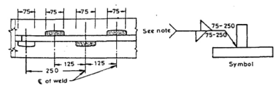
Staggered intermittent welds are an exception to the alignment rule for both symmetrical and non-symmetrical symbols. These welds are intentionally staggered or offset, creating a specific pattern that deviates from the usual alignment requirements. Staggered intermittent welds are often employed for specific purposes, such as stress distribution or enhancing joint strength.
Conclusion
Weld symbols serve as a universal language for communicating welding specifications and requirements. Understanding the distinction between symmetrical and non-symmetrical weld symbols is vital for accurate interpretation and successful implementation of welding processes.
By aligning symmetrical weld symbols across the reference line and aligning the leftmost points of contact for non-symmetrical symbols, welders can effectively decode the intended joint configurations and welding parameters.
It is essential for welders, fabricators, and engineers to familiarize themselves with these welding standards and symbols to ensure consistent and reliable welding practices. Clear communication and understanding of weld symbols contribute to the production of high-quality welds and ultimately result in robust and reliable welded structures.

